Siboor
Siboor Web Store
  • ※Welcome to Siboor
    • How to get help?
    • Agreement & Support
    • Friendly Links
    • Tool Guide
  • ※SIBOOR TRIDENT [JUNE]
    • Bill of Materials
    • The Build
      • Printed Parts(Oct/17)
      • Assembly manual
      • Initial Startup(Dec/05)
      • Initial Startup Checks[Nov/28]
      • Slicer Setup[Nov/28]
      • First Print
      • Ssh Quick Guide
    • Tuning Guides
      • Temperature calibration
      • Calibration Belt
      • Measuring Resonances
      • Filament Tuning
      • Pressure advance
      • Print Tuning
    • ⑤Maintenance Guide
    • FAQ(Oct/17)
      • Unused Ports Overview
      • Product specs
      • Cartographer to Survey Touch mode[Nov/26]
      • [New]Klipper LEDHelper Error Fix Tutorial
      • [New]Phaetus Rapido2 Heatblock Replacement Guide
      • [New] CB2 Timer too close
    • CNC Trident AWD
  • ※SIBOOR 2.4 R2 [AUG]
    • Bill of Materials
    • The Build
      • Printed Parts
      • Assembly manual
        • ① SIBOOR 2.4 R2 Aug
        • ② Stealthburner
        • ③ Nevermore V6
        • ※ CHAOTICLAD CNC KIT
        • ※ Tap Probe
      • Initial Startup[Dec/05]
      • Initial Startup Checks[Nov/26]
      • Slicer Setup[Nov/26]
      • First Print
      • Ssh Quick Guide
    • Tuning Guides
      • Temperature calibration
      • Calibration Belt
      • Measuring Resonances
      • Filament Tuning
      • Pressure advance
      • Print Tuning
    • Maintenance Guide
    • FAQ
      • Product specs
      • Cartographer to Survey Touch mode[Nov/26]
      • Octopus Pro PIN
  • ※SIBOOR 0.2 R1 [AUG]
    • Bill of Materials
    • The Build
      • Printed Parts
      • Assembly manual
        • Wiring Supplementary
        • Metal Version Supplementary
      • Initial Startup
      • Initial Startup Checks
      • Slicer Setup
      • First Print
      • Ssh Quick Guide
    • Tuning Guides
      • Calibration Belt
      • Measuring Resonances
      • Filament Tuning
      • Pressure advance
      • Temperature calibration
      • Print Tuning
    • Maintenance Guide
    • FAQ(Oct/3)
      • Product specs
      • FLY Gemini V3 Pin
  • ※E3-SW CONVERSION
    • Bill of Materials
    • The Build
      • Preparations
        • Printed Parts
        • Heat Set Inserts
        • Extrusion Tapping
      • Assembly manual
      • 接线说明
        • Creality 4.2.2 board
        • SKR Mini E3 V2 board
        • SKR Mini E3 V3 board
        • SKR Pico board
      • 首次启动
      • 首次启动检查
      • 切片器设置
      • Ssh Quick Guide
    • Tuning Guides
      • Calibration Belt
      • Measuring Resonances
      • Filament Tuning
      • Pressure advance
      • Temperature calibration
      • Print Tuning
    • Maintenance Guide
    • FAQ
      • Product specs
  • ※SIBOOR ERCF V2
    • Build of Materials
    • The Build
      • ①Print necessary parts
      • ②Assembly manual
      • ③Connect ERCF to the printer
      • ④Install Happy Hare
      • ⑤ Install KlipperScreen - Happy Hare
      • ⑥Validate you hardware configuration
      • ⑦Calibration Steps
      • ⑧Basic Operation
      • 切片设置
    • Tuning Guides
    • Maintenance Guide
    • FAQ
      • Product specs
      • EBB MMB V1.1 PIN
  • ※Other Products
    • CNC Trident AWD
      • Bill of Materials
      • FAQ
    • V0 Display Screen
    • V0 Krigami Bed
    • Klipper Expander
      • Overview of Features
      • Configuration Tutorial
      • Flashing Instructions
      • FAQ
    • RGB PCB LIGHT
    • LED Effect Notes
      • Wiring Guide
      • Installing LED Effects Software
      • Configuring the strips
      • Configuring the effects
      • [Advanced]Effect Layer Blending
      • FAQ
Powered by GitBook
On this page
  • Basic
  • Indicator LEDs
  • Switch (RST)
  • I2C Header (PF0, PF1)
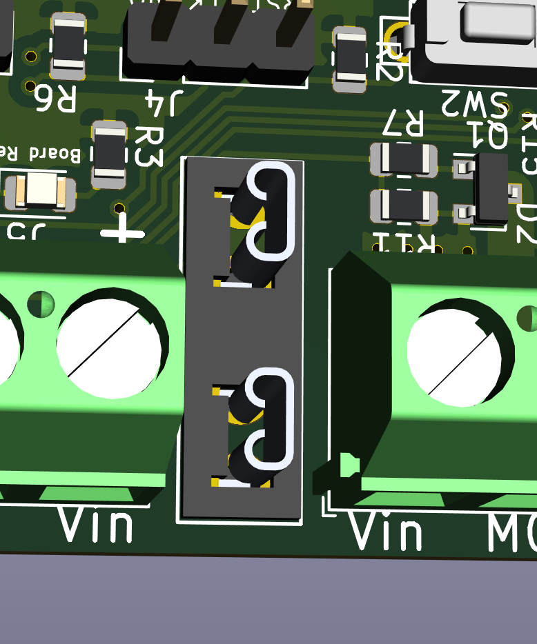
  • Power In
  • Fuse
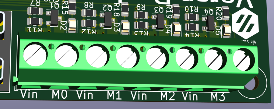
  • Mosfets (PA0, PA1, PA2, PA3)
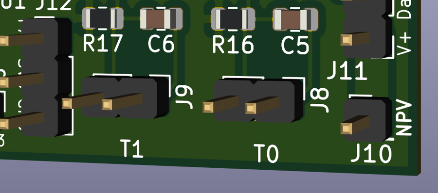
  • Thermistors (PA5, PA6)
  • Neopixel header (PB1)
  • Setup
  • Advanced
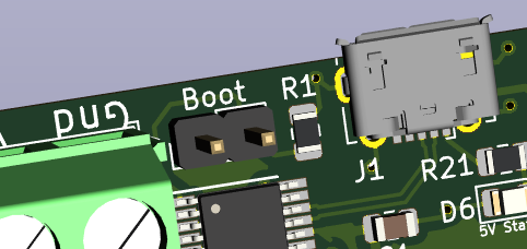
  • Boot Jumper
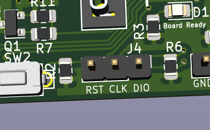
  • SWD header (PA13, PA14, RST)
  • GPIO (PA7))
  • Testing
  • Debugging
  • Basic troubleshooting:
  1. ※Other Products
  2. Klipper Expander

Overview of Features

PreviousKlipper ExpanderNextConfiguration Tutorial

Last updated 7 months ago

Please note that this document is sourced from the following link:

Welcome to your new Klipper Expander! This document outlines the common features of the board that you are likely to use.

Basic

First we will go through the basic functionality of the board that most users will be looking for.

Indicator LEDs

There are 3 status indicator LEDs on the board:

  • 5v Status near the USB port indicates that there is 5V present and feeding the board (D6)

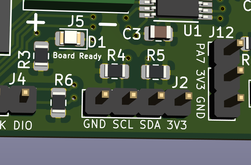
  • Board Ready near the IC indicates that the board is communicating with Klipper (D1)

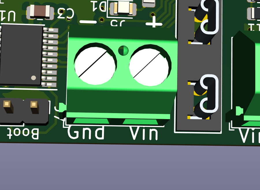
  • Vin status indicates that there is power present on the Vin and GND feeding the board through the screw terminals (D7)

  • 4 indicator LEDs (D2-D5) near each of the MOSFETs and screw terminals, these indicate if the MOSFET is enabled

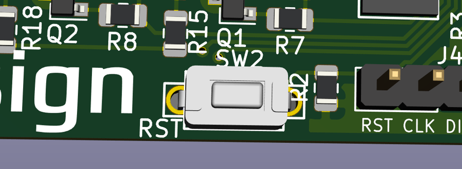
Switch (RST)

There is one switch, labeled RST. This resets the board

I2C Header (PF0, PF1)

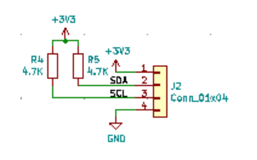
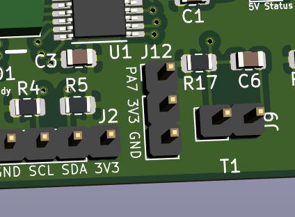
Contains a 3.3V I2C bus for connecting displays, and other sensors such as enviromental sensors and breakout expanders. This plugs into J2

Both SCL and SDA pins are pulled up to 3V3 with a 4.7k resistor

Example display configuration:

[display]
lcd_type: sh1106
i2c_bus: i2c1a

Power In

Vin and GND are for feeding power to the Mosfets, this can be any voltage under 50V

Fuse

The fuse is a micro blade type fuse and should be chosen to the maximum draw of all of the MOSFET fed devices.

For example, if you are running a 40W heater, 2 5W fans and 1 2W fan, you will need a total of 62W of power. At 24V, this would translate to 62W/24V = 2.58A. The closest fuse might be a 5A fuse, which is recommended you should use.

Maximum power should not exceed 12A as the MOSFETs are each rated to a maximum of 3A.

Mosfets (PA0, PA1, PA2, PA3)

4 x 4 3A Amp mosfets for controlling LED's, Heater, Fans, and other accessories Connected to pins PA0, PA1, PA2 and PA3

Example configuration:

[output_pin mosfet0]
pin: expander:PA0
value: 0
shutdown_value: 0

You may need to change expander: to match your expander mcu name

Thermistors (PA5, PA6)

2 thermistor inputs that use a 4.7K pullup resistor (Klipper default) Connected to pins PA5 and PA6

Example configuration for a standalone thermistor (Not tied to a bed or hotend):

[temperature_sensor t0]
sensor_type: ThermistorType
sensor_pin: expander:PA6
gcode_id: T0
[temperature_sensor t1]
sensor_type: ThermistorType
sensor_pin: expander:PA5
gcode_id: T1

You may need to change expander: to match your expander mcu name

Neopixel header (PB1)

Header for using neopixels. There is a single power input pin (NPV) that you can supply with the voltage your strip needs (5V/12V) and it passes it to the three pin header (Vin, Data, Ground) Connected to J1, which has a NPV supplied voltage, GND and PB1

Example configuration:

[neopixel Pixel]
pin: expander:PB1
chain_count: 1
initial_RED: 0.9
initial_GREEN: 0.3
initial_BLUE: 0.0

You may need to change expander: to match your expander mcu name

Setup

Advanced

Here are some more advanced features and details about the board

Boot Jumper

This jumper needs to be installed to put the board in DFU mode to flash it with the klipper firmware. The board will show up as "Device in DFU Mode" to lsusb and then should show up in dfu-util --list

SWD header (PA13, PA14, RST)

This header is used if you SOMEHOW manage to brick the device beyond a BOOT jumper reset.

GPIO (PA7))

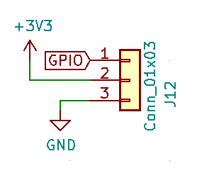
The GPIO header J12 (PA7,3V3,GND) is available for creative uses.

Examples of what this can be used for include external mosfet, relay or a door open sensor

PA7 is connected directly to the STM32 with no pullups

Testing

Included configuration file will allow you to startup the Expander without another MCU to validate all features are functional.

You will need the following devices:

  • Power supply (5V is easiest)

  • 4 x devices for MOSFET that will work at Power supply voltage

  • Neopixel with appropriate dupont headers (WS2812b for 5V or WS2811 for 12V)

  • 2 Thermistors with dupont or JST headers

  • Raspberry Pi or another computer running Klipper

Use the Example configuration supplied in this repository

# This configuration will allow you to run a Klipper Expander standalone, with no other MCU
# This is helpful for testing

[printer]
kinematics: none
max_velocity: 500
max_accel: 3000

[mcu]
serial:  /dev/serial/by-id/usb-Klipper_stm32f042x6_1F00200014434E5333333920-if00

[output_pin mosfet0]
pin: PA0
value: 0
shutdown_value: 0

[output_pin mosfet1]
pin: PA1
value: 0
shutdown_value: 0

[output_pin mosfet2]
pin: PA2
value: 0
shutdown_value: 0

[output_pin mosfet3]
pin: PA3
value: 0
shutdown_value: 0

# Status LED lights when klipper connects
[static_digital_output onboardLED]
pins: !PA4

[neopixel Pixel]
pin: PB1
chain_count: 1
initial_RED: 0.9
initial_GREEN: 0.3
initial_BLUE: 0.0

[display]
lcd_type: sh1106
i2c_bus: i2c1a

# Other Pins
# GPIO = PA7

[temperature_sensor t0]
sensor_type: ATC Semitec 104GT-2
sensor_pin: PA6
gcode_id: T0

[temperature_sensor t1]
sensor_type: ATC Semitec 104GT-2
sensor_pin: PA5
gcode_id: T1

When the Expander starts up you should see:

  • All 3 Status LEDs light up

  • None of the MOSFETs light up

  • Neopixel will be orange

  • Display will have a typical 3d printer interface

Other steps:

  • Run a M105 to get temperature readings

Debugging

Sometimes problems happen, here is how you can fix them

Basic troubleshooting:

  • Set in DFU mode and reflash

  • Remove unused sections in printer.cfg

  • Disconnect devices and test

\

\

For setup instructions, check .

Display (like this one: )

Execute the file to cycle through the MOSFET pins

Here
https://stm32-base.org/guides/connecting-your-debugger.html
Adafruit OLED Display
test.gcode
https://github.com/VoronDesign/Voron-Hardware/tree/master/Klipper_Expander/Documentation