# ※Welcome to Siboor

Innovating 3D Printing

**Our Story**\
Shenzhen SIBOOR Technology Culture Co., Ltd. was founded in 2020 by a group of young and passionate creators dedicated to revolutionizing the 3D printing industry. Our name, "SIBOOR," represents our relentless pursuit of knowledge and innovation. The additional "O" adds a powerful resonance, reminiscent of a booming sound, akin to the impact of an earthquake. This symbolizes our ambition to shatter boundaries in technology and capture the attention of enthusiasts.

**Our Mission**\
We strive to enhance product quality and user experience, empowering creators and makers worldwide to bring their ideas to life. We are not just a product supplier; we are partners with innovators globally, moving forward together towards technological advancement.

**Core Products**

* **High-Quality FDM 3D Printer Accessories**
* **DIY VORON Series Kits**
* **Upcoming Large DIY Printers and Advanced CNC Kits**

**Future Outlook**\
As we continue to innovate, we invite you to join us on this exciting journey to shape the future of 3D printing.

**Explore Our Products**

***

<figure><img src="/files/tEYNILqeENXNpY6NL8Tw" alt=""><figcaption></figcaption></figure>


# How to get help?

Welcome to Siboor, we provide high quality 3D printer products with outstanding service. If you have any questions, or need any help, please feel free to join our Discord, it currently has over 1600 members, and is growing rapidly! ！

We will aim to update and these documents as often as we can, if anything is out of date or missing, please let us know and we will aim to get this updated as soon as possible.

<figure><img src="/files/UhzLUfnr8Tcu3pBPJag8" alt=""><figcaption></figcaption></figure>

Discord Join Link: <https://discord.gg/RNDjXghVg9>


# Agreement & Support

***

#### 【Safety Warnings】

**1. Adults Only:** This kit is only available for purchase by adults with full civil capacity. SIBOOR reserves the right to refuse technical support and wiring guidance to minors, as operating high-voltage electrical systems requires professional knowledge and experience. Minors may lack the necessary skills and judgment to safely handle such tasks, posing serious risks of injury or damage.

**2. High Voltage Risk:** This kit involves wiring and testing of 110/220V high-voltage circuits. Always seek assistance from qualified professionals; do not attempt to operate it yourself. Before working on any wiring, ensure the printer is unplugged and the capacitors in the power supplies have discharged.Always proceed with caution to prevent fires and other hazards.

**3. Use of Dangerous Tools:** Installation requires tools such as soldering irons and pliers, which can cause burns or injuries if not handled properly. Please exercise caution.

**4. Installation Guidance:** Before beginning the installation, carefully read the assembly manual to ensure correct operation.

**5. Safety Warning:** Before powering on, check the wiring diagram to confirm the connections for the neutral wire, live wire, ground wire, and the positive and negative terminals of the 5V devices are correct. Even professionals can overlook these details, so do not skip this step. Failing to check may cause short circuits, potentially damaging sensitive components like Board，Tool Board，RGB lights, Cartographer V3, and servos, leading to irreversible harm.

**6. Risk of Damage:** Never plug or unplug any device while the printer is powered. This not only poses a safety hazard but also risks damaging electronic components. In particular, stepper drivers can be easily damaged by connecting or disconnecting stepper motors while powered.&#x20;

#### 【Disclaimer】

1. **Liability Waiver**: SIBOOR is not responsible for accidents caused by improper operation, violations of instructions, unauthorized modifications, or failure to follow the safety warnings.
2. **Warranty Coverage**: All components of the kit, except for custom parts and those with special declarations, are covered by the warranty.
3. **Non-Warranty Issues**: Damages that are not related to product quality do not fall under the warranty.

#### 【Warranty Policy】

As SIBOOR 3D printer kits consist of multiple independent components, the warranty is applied to individual parts rather than the entire kit. If, after inspection, no external damage or unauthorized modifications are found, and the issue is due to material, craftsmanship, or functionality defects, SIBOOR will offer free repair or replacement of the affected parts. Warranty periods vary depending on the component.

1. **Warranty Coverage**:
   * **Manufacturing Defects**: Issues caused by defects in the manufacturing process.
   * **Material Issues**: Damage caused by defective materials.
2. **Warranty Period**:
   * **12-month warranty**: Power supply, motors, relays, silicone heating pads, linear rails.
   * **6-month warranty**: Mainboard, display screen, host（PI）, CAN board，Pulleys, idlers, bearings.
   * **3-month warranty**: Fans, extruder components, Drivers, RGB lights, belts,endstop switch，Heating Rod, Thermistor，cables.
3. **Parts Not Covered or with Limited Warranty**:
   * **Consumables (No Warranty)**: Consumables such as hotends, nozzles, printing Plate, PTFE tubes, Activated Carbon，and other expendable items are not covered under the warranty.

#### 【Warranty Exclusions】

SIBOOR reserves the right to deny warranty service in the following cases:

1. **User Damage**: Damage caused by user errors such as short circuits, water ingress, corrosion, or unauthorized modifications.
2. **Improper Installation**: Damage resulting from incorrect installation, use, or testing not following the provided manual.
3. **Cosmetic Damage**: Wear and tear or scratches that do not affect the product's performance.
4. **Force Majeure**: Damage caused by natural disasters such as earthquakes, fires, floods, or other uncontrollable events.
5. **Overuse**: Damage caused by exceeding the design load or using incompatible accessories.
6. **Non-Original Parts**: Damage resulting from the use of non-SIBOOR original parts or unauthorized modifications.

#### 【Warranty Claim Process】

1. **Contact Support**: If you encounter any issues, contact SIBOOR after-sales support, providing your order number and a description of the problem. It is recommended to include photos or videos.
2. **Submit Evidence**: Provide relevant evidence (photos or videos) as requested to verify the issue.
3. **Product Inspection**: You may be required to return the product for inspection or receive a remote diagnosis.
4. **Resolution**: Once the issue is confirmed to be within the warranty scope, SIBOOR will offer repair, replacement, or another appropriate solution.

#### 【Other Notes】

1. If no warranty claim is made within the specified time, it will be considered a waiver of rights, unless the customer can provide sufficient justification for the delay, and the reason is accepted by SIBOOR.
2. SIBOOR reserves the final right of interpretation for this warranty policy.

***

For further inquiries or assistance, please contact us:

* **Email ①**: <k13724736409@gmail.com>
* **Email ②:**&#x64;<avid.huss@hsc.wvu.edu>
* **Discord**:SIBOOR-Slipper

Revised: 2024-9-24


# Friendly Links

### ※Commonly Used Websites

<table><thead><tr><th width="202">Web Name</th><th>Function Description</th></tr></thead><tbody><tr><td><a href="https://github.com/Lzhikai">Siboor Github</a></td><td>Siboor's GitHub repository contains STL files, manuals, configuration files, and more.</td></tr><tr><td><a href="https://www.klipper3d.org/">Klipper documentation</a></td><td>The Klipper documentation website outlines the features and usage methods of the Klipper firmware.</td></tr><tr><td><a href="https://docs.fluidd.xyz/">Fluidd docs</a></td><td>Provides a modern web interface for users to monitor and manage Klipper printer functions in real time.</td></tr><tr><td><a href="https://docs.mainsail.xyz/">Mainsail docs</a></td><td>Powerful features with a user-friendly interface, helping Klipper users easily control their printers and manage resources.</td></tr><tr><td><a href="https://vorondesign.com/">Voron Design</a></td><td>Provides detailed information, resources, and support for the VORON 3D printer, dedicated to community-driven open-source printer design.</td></tr><tr><td><a href="https://docs.cartographer3d.com/">Cartographer docs</a></td><td>Provides download and installation guides for the Cartographer Probe software, along with advanced usage methods and an overview of common issues.</td></tr><tr><td><a href="https://bttwiki.com/#follow-us-on-social-media-to-get-more-news">Bigtreetech WIKI</a></td><td>Provide relevant information and user guides for the BTT products included in the kit, as well as other products sold by Bigtreetech.</td></tr><tr><td><a href="https://mellow.klipper.cn/#/">Fly docs</a></td><td>Provides download and user guides for products, including motherboards, from Fly.</td></tr><tr><td><a href=" https://github.com/bigtreetech/KlipperScreen">BTT KlipperScreen</a></td><td>Provides download and installation guides for BTT KlipperScreen software, enabling users to intuitively control and monitor their Klipper printers via touchscreen.</td></tr></tbody></table>

***

### ※Popular 3D Model Websites

<table><thead><tr><th>Web Name</th><th width="219">Types</th><th width="111">Free/paid</th><th width="118">3D Model</th></tr></thead><tbody><tr><td><a href="https://www.printables.com/">printables</a></td><td>Databases</td><td>Free</td><td>★★★★★</td></tr><tr><td><a href="https://makerworld.com.cn/zh/makerlab?from=bambustudio">Makerworld</a></td><td>Databases</td><td>Free</td><td>★★★★★</td></tr><tr><td><a href="https://link.zhihu.com/?target=https%3A//www.thingiverse.com/">Thingiverse</a></td><td>Databases</td><td>Free</td><td>★★★★★</td></tr><tr><td><a href="https://link.zhihu.com/?target=https%3A//cults3d.com/en">Cults</a></td><td>Markets</td><td>Free, paid</td><td>★★★★</td></tr><tr><td><a href="https://link.zhihu.com/?target=https%3A//www.cgtrader.com/">CGTrader</a></td><td>Markets</td><td>Free, paid</td><td>★★★★</td></tr><tr><td><a href="https://link.zhihu.com/?target=https%3A//www.myminifactory.com/">MyMiniFactory</a></td><td>Markets</td><td>Free, paid</td><td>★★★★</td></tr><tr><td><a href="https://link.zhihu.com/?target=https%3A//pinshape.com/">Pinshape</a></td><td>Markets</td><td>Free, paid</td><td>★★★★</td></tr><tr><td><a href="https://link.zhihu.com/?target=https%3A//www.turbosquid.com/Search/3D-Models/free/stl">TurboSquid</a></td><td>Databases</td><td>Free, paid</td><td>★★★★</td></tr><tr><td><a href="https://link.zhihu.com/?target=https%3A//www.prusaprinters.org/prints">PrusaPrinters</a></td><td>Databases</td><td>Free</td><td>★★★</td></tr><tr><td><a href="https://link.zhihu.com/?target=https%3A//3dexport.com/">3DExport</a></td><td>Markets</td><td>Free, paid</td><td>★★★</td></tr><tr><td><a href="https://link.zhihu.com/?target=https%3A//www.youmagine.com/">YouMagine</a></td><td>Databases</td><td>Free</td><td>★★★</td></tr><tr><td><a href="https://link.zhihu.com/?target=http%3A//3dprint.nih.gov/">NIH 3D Print Exchange</a></td><td>Databases</td><td>Free</td><td>★★</td></tr><tr><td><a href="https://link.zhihu.com/?target=https%3A//www.threeding.com/index.php">Threeding</a></td><td>Markets</td><td>Free, paid</td><td>★★</td></tr><tr><td><a href="https://link.zhihu.com/?target=https%3A//free3d.com/free-3d-models/3d-printable%3F">Free3D</a></td><td>Databases</td><td>Free, paid</td><td>★★</td></tr><tr><td><a href="https://link.zhihu.com/?target=https%3A//grabcad.com/">GrabCAD Library</a></td><td>Databases</td><td>Free</td><td>★★</td></tr><tr><td><a href="https://link.zhihu.com/?target=https%3A//www.redpah.com/">Redpah</a></td><td>Markets</td><td>Free, paid</td><td>★★</td></tr><tr><td><a href="https://link.zhihu.com/?target=http%3A//www.3dshook.com/">3DShook</a></td><td>Subscription service</td><td>Free, paid</td><td>★★</td></tr><tr><td><a href="https://link.zhihu.com/?target=https%3A//3d-gallery.xyzprinting.com/en-US/gallery/">XYZprinting 3D Gallery</a></td><td>Markets</td><td>Free, paid</td><td>★★</td></tr><tr><td><a href="https://link.zhihu.com/?target=https%3A//library.zortrax.com/">Zortrax Library</a></td><td>Markets</td><td>Free, paid</td><td>★</td></tr><tr><td><a href="https://link.zhihu.com/?target=https%3A//libre3d.com/">Libre3D</a></td><td>Databases</td><td>Free</td><td>★</td></tr><tr><td><a href="https://link.zhihu.com/?target=https%3A//fab365.net/">Fab365</a></td><td>Markets</td><td>Free, paid</td><td>★</td></tr><tr><td><a href="https://link.zhihu.com/?target=https%3A//nasa3d.arc.nasa.gov/models/printable">NASA</a></td><td>Databases</td><td>Free</td><td>★</td></tr><tr><td><a href="https://link.zhihu.com/?target=https%3A//digilab.dremel.com/resources/lesson-plans">Dremel Lesson Plans</a></td><td>Databases</td><td>Free</td><td>/</td></tr><tr><td><a href="https://link.zhihu.com/?target=https%3A//www.instructables.com/">Instructables</a></td><td>Databases</td><td>Free</td><td>/</td></tr><tr><td><a href="https://link.zhihu.com/?target=https%3A//www.yeggi.com/">Yeggi</a></td><td>Internet search engine</td><td>Free, paid</td><td>/</td></tr><tr><td><a href="https://link.zhihu.com/?target=https%3A//www.stlfinder.com/">STLFinder</a></td><td>Internet search engine</td><td>Free, paid</td><td>/</td></tr><tr><td><a href="https://link.zhihu.com/?target=https%3A//www.3dfindit.com/%3Flang%3Den_GB">3DFindIt</a></td><td>Internet search engine</td><td>Free, paid</td><td>/</td></tr><tr><td><a href="https://link.zhihu.com/?target=https%3A//thangs.com/">Thangs</a></td><td>Internet search engine</td><td>Free, paid</td><td>/</td></tr></tbody></table>


# Tool Guide

* <mark style="color:blue;">**`Prepare`**</mark>：You need to prepare or purchase it yourself.
* ✅：This product is already included in the kit.
* ❌：This kit does not require this tool.
* ❔：This tool is not essential and can be prepared based on the actual situation.

<table><thead><tr><th width="228">Tool Name</th><th>Voron2.4</th><th>Trident</th><th>Voron0.2</th><th>E3-SW</th><th>ERCF V2</th></tr></thead><tbody><tr><td><ol><li>Hex Wrench</li></ol></td><td>✅</td><td>✅</td><td>✅</td><td><mark style="color:blue;"><strong><code>Prepare</code></strong></mark></td><td><mark style="color:blue;"><strong><code>Prepare</code></strong></mark></td></tr><tr><td><ol start="2"><li>Screwdriver</li></ol></td><td>✅</td><td>✅</td><td>✅</td><td><mark style="color:blue;"><strong><code>Prepare</code></strong></mark></td><td>❌</td></tr><tr><td><ol start="3"><li>Soldering Tools</li></ol></td><td><mark style="color:blue;"><strong><code>Prepare</code></strong></mark></td><td><mark style="color:blue;"><strong><code>Prepare</code></strong></mark></td><td><mark style="color:blue;"><strong><code>Prepare</code></strong></mark></td><td><mark style="color:blue;"><strong><code>Prepare</code></strong></mark></td><td><mark style="color:blue;"><strong><code>Prepare</code></strong></mark></td></tr><tr><td><ol start="4"><li>Crimping Tool</li></ol></td><td>❔</td><td>❔</td><td>❔</td><td><mark style="color:blue;"><strong><code>Prepare</code></strong></mark></td><td>❔</td></tr><tr><td><ol start="5"><li>Measuring Tools</li></ol></td><td><mark style="color:blue;"><strong><code>Prepare</code></strong></mark></td><td><mark style="color:blue;"><strong><code>Prepare</code></strong></mark></td><td><mark style="color:blue;"><strong><code>Prepare</code></strong></mark></td><td><mark style="color:blue;"><strong><code>Prepare</code></strong></mark></td><td><mark style="color:blue;"><strong><code>Prepare</code></strong></mark></td></tr><tr><td><ol start="6"><li>M5 TAP</li></ol></td><td>❌</td><td>❌</td><td>❌</td><td><mark style="color:blue;"><strong><code>Prepare</code></strong></mark></td><td>❌</td></tr><tr><td><ol start="7"><li>Cutting pliers</li></ol></td><td>✅</td><td><mark style="color:blue;"><strong><code>Prepare</code></strong></mark></td><td><mark style="color:blue;"><strong><code>Prepare</code></strong></mark></td><td><mark style="color:blue;"><strong><code>Prepare</code></strong></mark></td><td><mark style="color:blue;"><strong><code>Prepare</code></strong></mark></td></tr><tr><td><ol start="8"><li>Deburring Tool</li></ol></td><td>✅</td><td>❔</td><td>❔</td><td>❔</td><td>❔</td></tr><tr><td><ol start="9"><li>PTFE tube cutter</li></ol></td><td>✅</td><td>❔</td><td>❔</td><td>❔</td><td>❔</td></tr><tr><td><ol start="10"><li>502 glue, etc</li></ol></td><td>❔</td><td>❔</td><td>❔</td><td>❔</td><td>❔</td></tr><tr><td><ol start="12"><li>Thread Sealant</li></ol></td><td>❔</td><td>❔</td><td>❔</td><td>❔</td><td>❔</td></tr><tr><td><ol start="13"><li>Grease</li></ol></td><td><mark style="color:blue;"><strong><code>Prepare</code></strong></mark></td><td><mark style="color:blue;"><strong><code>Prepare</code></strong></mark></td><td><mark style="color:blue;"><strong><code>Prepare</code></strong></mark></td><td><mark style="color:blue;"><strong><code>Prepare</code></strong></mark></td><td>❔</td></tr></tbody></table>

{% hint style="info" %}
**Why is it necessary to prepare soldering tools?**&#x20;

Do I need to solder cables? During the assembly process of the kit, there is no need for soldering cables, but soldering tools are essential for using heat set inserts.
{% endhint %}


# ※SIBOOR BOOM \[January, 2026】

<figure><img src="/files/9uxq4SkETFAqJNOIEzMB" alt=""><figcaption></figcaption></figure>

**SIBOOR BOOM: An Open-Source CoreXZ 3D Printer Worth Building With Your Own Hands**

Welcome to the world of creation with the SIBOOR BOOM. This is more than just a 3D printer; it is an **open-source hardware platform designed for hands-on enthusiasts, family creators, and geek players.**

We believe true creation begins with understanding and control. Therefore, we chose not to deliver a sealed "black box." Instead, we honestly present **all the possibilities of a high-performance CoreXZ printer in the form of a parts kit.**

**Its core ethos is: open-source, customizable, built for learning and fun.**

**Why Choose the SIBOOR BOOM Kit?**

* **A Deep Learning Journey**: From assembling the precision aluminum extrusion frame to mounting the high-reliability hotend (Sherpa + E3D V6), to connecting the electrical system—every step is a thorough understanding of how a 3D printer works. This is not just about building a machine; it's about **mastering a skill**.
* **A Family Collaboration Project**: It offers an excellent opportunity for parent-child or partner collaboration. In the process of studying the drawings together, tightening every screw in cooperation, and celebrating the machine's successful startup, what you build is **not just the machine, but also (tacit understanding) and memories**.
* **A Platform of Infinite Possibilities**: As an open-source project, you have complete access to all mechanical design files and firmware code. Whether upgrading linear rails, switching to a faster control board, or tuning a dedicated Klipper firmware, it evolves with your skills and ideas. This is **a printer that truly belongs to you, defined by you**.

**Technical Foundation: Designed for Reliable Performance**

Although delivered as a kit, the SIBOOR BOOM makes no compromises on its core configuration, ensuring excellent print potential upon completion:

* **Structure**: A sturdy 2020/2040 aluminum extrusion frame paired with a **CoreXZ motion system** lays the foundation for fast and precise printing.
* **Hotend**: Integrates the acclaimed **Sherpa Mini extruder** with the classic **E3D V6 hotend**, delivering powerful and stable extrusion performance.
* **Platform**: A **220W fast-heating aluminum heated bed** and a **double-sided textured PEI spring steel sheet** ensure excellent first-layer adhesion and easy model removal.
* **Electrical**: A **filtered power switch**, **300W 24V switching power supply**, and an **open-source mainboard** provide stable power while reserving vast room for upgrades (such as easily upgrading to Klipper).

We have prepared detailed, illustrated assembly guides, an active community for support, and continuously updated optimization solutions. The SIBOOR BOOM kit invites you to step into an immersive journey of creation and experience the full sense of accomplishment from zero to one, from parts to a work of art.

**Your Creation Starts Now.**


# Bill of Materials

| Part Description                                                        | /                   | Qty      |
| ----------------------------------------------------------------------- | ------------------- | -------- |
| M2x10 Self Tapping Hex Screw                                            | Black Nickel Plated | 7        |
| M3x4 BHCS                                                               | Black Nickel Plated | 3        |
| M3x6 BHCS                                                               | Black Nickel Plated | 9        |
| M3x8 BHCS                                                               | Black Nickel Plated | 13       |
| M3x10 BHCS                                                              | Black Nickel Plated | 3        |
| M3x12 BHCS                                                              | Black Nickel Plated | 8        |
| M3x16 BHCS                                                              | Black Nickel Plated | 14       |
| M3x20 BHCS                                                              | Black Nickel Plated | 13       |
| M3x25 BHCS                                                              | Black Nickel Plated | 4        |
| M3x30 BHCS                                                              | Black Nickel Plated | 5        |
| M3x35 BHCS                                                              | Black Nickel Plated | 2        |
| M3x40 BHCS                                                              | Black Nickel Plated | 1        |
| M3x6 FHCS                                                               | Black Nickel Plated | 5        |
| M3x10 FHCS                                                              | Black Nickel Plated | 7        |
| M3x8 SHCS                                                               | Black Nickel Plated | 13       |
| M3x12 SHCS                                                              | Black Nickel Plated | 13       |
| M3x16 SHCS                                                              | Black Nickel Plated | 2        |
| M3x20 SHCS                                                              | Black Nickel Plated | 5        |
| M3x30 SHCS                                                              | Black Nickel Plated | 9        |
| M3x40 SHCS                                                              | Black Nickel Plated | 2        |
| M4x6 BHCS                                                               | Black Nickel Plated | 7        |
| M4x10 FHCS                                                              | Black Nickel Plated | 5        |
| M5x8 BHCS                                                               | Black Nickel Plated | 7        |
| M5x10 BHCS                                                              | Black Nickel Plated | 24       |
| M5x12 BHCS                                                              | Black Nickel Plated | 10       |
| M5x16 BHCS                                                              | Black Nickel Plated | 18       |
| M5x25 BHCS                                                              | Black Nickel Plated | 3        |
| M5x30 BHCS                                                              | Black Nickel Plated | 4        |
| M5x35 BHCS                                                              | Black Nickel Plated | 2        |
| M5x40 BHCS                                                              | Black Nickel Plated | 2        |
| M5x10 SHCS                                                              | Black Nickel Plated | 3        |
| M5x16 SHCS                                                              | Black Nickel Plated | 5        |
| M5x20 SHCS                                                              | Black Nickel Plated | 6        |
| M5x25 SHCS                                                              | Black Nickel Plated | 3        |
| M5x45 SHCS                                                              | Black Nickel Plated | 2        |
| M3 Hex Nut                                                              | Black Nickel Plated | 13       |
| M5 Hex Nut                                                              | Black Nickel Plated | 5        |
| M5 Flange Nut                                                           | /                   | 3        |
| M5 Washer, 1mm Thick, Stainless Steel                                   | /                   | 19       |
| M3 Spring Nut (T-Nut)                                                   | /                   | 21       |
| M5 Spring Nut (T-Nut)                                                   | /                   | 54       |
| M3 Heat-Set Insert (Brass, M3x4x5)                                      | /                   | 55       |
| M3x8+6 Hexagonal Brass Spacer                                           | /                   | 4        |
| M3x20+6 Hexagonal Brass Spacer                                          | /                   | 4        |
| M3x20 Ø6 Cylinder (V0.2 style) Aluminum Double-Round Head               | /                   | 2        |
| M6 SHCS with M4 Inner Thread (Tapped)                                   | /                   | 4        |
| 6x3mm Round Neodymium Magnet                                            | /                   | 4        |
| F695ZZ Bearing                                                          | /                   | 18       |
| A Extrusion                                                             | /                   | 2        |
| B Extrusion                                                             | /                   | 2        |
| C Extrusion                                                             | /                   | 2        |
| D Extrusion                                                             | /                   | 1        |
| E Extrusion                                                             | /                   | 1        |
| Ø10mm Chrome Plated Shaft, 350mm length                                 | /                   | 2        |
| Ø10mm Chrome Plated Shaft, 350mm length, Single-end M5 Tapped           | /                   | 2        |
| Y-Axis Metal Bracket                                                    | /                   | 1        |
| LM10LUU Linear Bearing, Chrome Plated & Anti-Rust                       | /                   | 2        |
| LM10UU Linear Bearing, Chrome Plated & Anti-Rust                        | /                   | 2        |
| Lindeng MGN12H Linear Rail, 300mm, Preloaded                            | /                   | 1        |
| Lindeng MGN9H Linear Rail, 50mm, Preloaded                              | /                   | 1        |
| SIBOOR-42STH38-1504B Stepper Motor                                      | Siboor              | 3        |
| SIBOOR-14STH20-1004B Stepper Motor                                      | Siboor              | 1        |
| BMG Extruder Assembly Kit (Red Reduction Gear)                          | Siboor              | 1        |
| GT2 20T Idler Pulley, 6mm Width, 5mm ID                                 | Siboor              | 2        |
| GT2 20T Drive Pulley, 9mm Width, 5mm ID                                 | Siboor              | 1        |
| GT2 20T Idler Pulley, 9mm Width, 5mm ID                                 | Siboor              | 1        |
| MKS Robin Nano V3.1                                                     | /                   | 1        |
| MKS Mini12864 V3                                                        | /                   | 1        |
| MKS TMC2209 Stepper Driver                                              | /                   | 4        |
| ChuangLian 300W 24V Power Supply                                        | CHUANGLIAN          | 1        |
| 24V 4010 Hydraulic Vortex Fan                                           | Siboor              | 2        |
| 24V 3010 Fan                                                            | Siboor              | 2        |
| Y-Axis Limit Switch                                                     | /                   | 1        |
| BOOM Adapter Board Extension Cable (MX3.0 14pin)                        | Siboor              | 1        |
| Ground Wire (Yellow, 1\*1.5mm², 30cm, Fork to Ring)                     | /                   | 1        |
| Power Supply Wire Set (Black & Red, 1\*1.5mm², 30cm, Fork to Pin)       | /                   | 2        |
| Heated Bed PCB Cable Set                                                | /                   | 1        |
| BOOM Hot-end adapter plate                                              | Siboor              | 1        |
| 24V 50W Green Heating Cartridge, 10cm wire (MX3.0 2pin)                 | /                   | 1        |
| NTC 3950 100K Thermistor, 10cm wire (Ø3x15mm Cylinder)                  | /                   | 1        |
| V6 Heater Block                                                         | /                   | 1        |
| V6 Silicone Sock                                                        | /                   | 1        |
| V6 Heat Sink (M7 Thread)                                                | /                   | 1        |
| V6 Nozzle 0.4mm                                                         | /                   | 1        |
| V6 Heat Break (M7 Thread, for 2\*3 PTFE Tube)                           | /                   | 1        |
| PTFE Tube 2\*3 (consumable, for heat break), 10cm                       | /                   | 0.1meter |
| Gates GT2 Timing Belt, 6mm Width, 1.5m Length                           | Gates               | 3        |
| Standard GT2 Timing Belt, 9mm Width, 1m Length                          | /                   | 1        |
| PTFE Tube 4x2                                                           | /                   | 1 m      |
| A-Type Skirt Panel                                                      | /                   | 2        |
| B-Type Skirt Panel                                                      | /                   | 1        |
| C-Type Skirt Panel                                                      | /                   | 1        |
| Electronics Cover Plate                                                 | /                   | 1        |
| Electronics Base Plate                                                  | /                   | 1        |
| BOOM-PRO Printing Sheet                                                 | Siboor              | 1        |
| BOOM 24V 220W Aluminum Heated Bed                                       | Siboor              | 1        |
| Little rubber feet                                                      | /                   | 4        |
| 10x11 Openable Cable Drag Chain, 17 Sections (Excluding End Connectors) | /                   | 1        |
| 10x11 Openable Cable Drag Chain, 25 Sections (Includes End Connectors)  | /                   | 1        |
| Power Filter with Wire (Trident shared)                                 | /                   | 1        |
| 6-Piece Wrench Set                                                      | /                   | 1        |
| Flat/Phillips Double-Ended Screwdriver (Retractable)                    | /                   | 1        |
| Nylon Cable Tie (Small) 3\*150mm                                        | /                   | 20       |
| Adjustable Cable Tie Mount Base (Black CL-1 with 3M Tape)               | /                   | 5        |
| Flush Cutter                                                            | /                   | 1        |
| TF Card (Micro SD Card) 8GB Memory + Card Holder                        | Sandisk             | 1        |
| Sample Filament 200g, Sealed Spool                                      | /                   | 1        |
| Door Closer (Black All-Rubber, 1000g Tension)                           | /                   | 1        |
| Full set of prints（ABS+）                                                | SUNLU               | 1        |


# The Build


# Printed Parts

### ※Printed Parts Guideline

The Voron Team has provided the following print guidelines for you to follow in order to have the best chance at success with your parts. There are often questions about substituting materials or changing printing standards, but we recommend you follow these.

| Setting                 | Recommendation                             |
| ----------------------- | ------------------------------------------ |
| 3D Printing Process     | Fused Deposition Modeling (FDM)            |
| Material                | ABS                                        |
| Infill Type             | Grid, Gyroid, Honeycomb, Triangle or Cubic |
| Layer Height            | 0.2mm                                      |
| Wall Count              | 4                                          |
| Extrusion Width         | Forced 0.4mm                               |
| Solid Top/Bottom layers | 5                                          |

### ※Download STL files

{% embed url="<https://github.com/Lzhikai/SIBOOR-S-BOOM-2026/tree/main/STLS>" %}


# Assembly manual

### ※Wiring diagram

{% hint style="info" %}
The latest version of the wiring diagram is placed here. Please refer to the most recent release for wiring.
{% endhint %}

<figure><img src="/files/0rXMwk07HBrvAapIfXEi" alt=""><figcaption></figcaption></figure>

### ※Assembly manual&#x20;

{% embed url="<https://github.com/Lzhikai/SIBOOR-S-BOOM-2026/blob/main/Manual/Assembly_Manual_SIBOOR_BOOM.pdf>" %}

<figure><img src="/files/jIqV3QKHMeEioOxKAAki" alt=""><figcaption></figcaption></figure>

### ※Assembly video

1. SIBOOR BOOM 3D Printer Kit – Part 1: Base Assembly

{% embed url="<https://www.youtube.com/watch?v=H04YAOBFILA>" %}

SIBOOR BOOM 3D Printer Kit – Part 2: Gantry Assembly

{% embed url="<https://www.youtube.com/watch?v=ANVqSYsU5dY>" %}

SIBOOR BOOM 3D Printer Kit – Part 3: Printhead and Electronics Installation

{% embed url="<https://www.youtube.com/watch?v=cPd8r0y2ptU>" %}


# Initial Startup

### ※Check Wiring

Before powering on, perform a final check of all connections:

* 110/220V wiring section
* 5V/24V wiring section
* Ensure all jumpers are inserted in the correct positions
* Verify all drivers are inserted into the appropriate driver slots and properly seated

<figure><img src="/files/0rXMwk07HBrvAapIfXEi" alt=""><figcaption></figcaption></figure>

With these instructions and icons, you can easily control the printer's menu and safety features.

### ※XYZ Homing Check

* Important: You need to be able to quickly stop the printer in case something goes wrong (e.g. the tool head goes the wrong direction). There are a few ways of doing this:
* There is a emergency reset icon underneath the encoder knob. Click on it to reboot marlin
* As a “nuclear” option, power off the printer with the power switch if something goes wrong. This is not ideal because it may corrupt the files on the SD card and to recover would require reinstalling everything from scratch.
* Once there is a tested process for stopping the printer in case of something going wrong, you can test X and Z movement. note: you will need to test X AND Y before you can correctly determine what adjustments are needed. First, Control -> Motion -> Homing ->Home X . This will only home X: The tool head should move up slightly and then move to the right until it hits the X endstop. If it moves any other direction, abort, take note, but still move on to testing Y. Next, test Y: Homing Y. The bed should move to the back of the printer until it hits the Y endstop.  \
  Next，test Z:Homing Z.The X and Y should move to the center of Axis. Then the toolhead should move up slightly and then move to the bottom until it hits the bed.

### ※Setting Z Offset

Before modifying your Z Offset, make sure that you have set your Z position to 0, and the nozzle is cleaned ,to do this you can run the following operation.                                                                           &#x20;

* Control -> Motion -> Homing -> Auto Home -> Motion -> Move Axis -> Move Z -> Move 0.025mm -> 000.000

<figure><img src="/files/URzjHE2LmsFdL9mYoNDW" alt=""><figcaption></figcaption></figure>

1. Place an A4 sheet on the platform.
2. Use the infoscreen to adjust the nozzle height relative to the bed.

* Move Z 0.025mm -> 000.025
* Move Z 0.025mm -> -000.025
* Once the offset has been perfectly calibrated apply , write down the Z Position. Then adjust Probe Z Offset.  \
  The Default Z offset is 2.00mm ,because the Z probe need this distance to be triggered after the nozzle touched the bed.
* use the following formula to calculate the Actual Z offset:
* Actual Z offset=Default Z offset + Z Position
* For example:
* Default Z offset：2.00mm
* Z Position:-000.230
* Actual Z offset:1.77mm

3. Store Settings:

* Control-> Configuration -> Store Settings -> Load Settings.

<figure><img src="/files/CJiJZPBULrRc5tEYIoUs" alt=""><figcaption></figcaption></figure>

4. Verify

* Retest:Perform the A4 sheet test when the Z Position is 0
* Adjust: Continue adjusting Probe Z Offset as needed until the first layer is accurate.

### ※Level bed

At this point everything is ready to Level bed.

* Control -> Motion -> Level Bed

<figure><img src="/files/e2Cku8NL0o5yjqfRivM2" alt=""><figcaption></figcaption></figure>

* The toolhead will automatically move to multiple preset point with Z Probe.  \
  The probe will contact the print bed at each point to take measurements.  \
  Do not touch the printer: The process is automatic; avoid any interference.
* After probing is complete, the screen will display "Leveling Complete".
* Save the mesh.
* Control-> Configuration -> Save Settings -> Load Settings.

### ※Filament Tuning

Purpose Flow calibration ensures that your printer's extruder accurately dispenses material, improving print quality.

Prerequisites Marlin2.1.X firmware installed and configured. Printer connected and set up.

Basic printer calibration (such as axis calibration) completed.

Steps

1. Preparation

* Confirm Printer Temperature: Ensure the hotend is heated to the appropriate printing temperature for your material. For PLA, set the hotend to around 200°C.
* Heat the hot end to 200 degrees Celsius.

<figure><img src="/files/OJIxrKjiZ9nFp0H3tXOX" alt=""><figcaption></figcaption></figure>

* Check Nozzle: Ensure the nozzle is clear and not clogged.
* Mark Material: Use a segment of material and make a mark at 100mm from the extruder gear.

2. Positioning and Extrusion

* Home the Printer: Home all axes to ensure the printer is in the correct starting position. This will move the print head to the center of the build plate, making it easier to observe.
* Extrude Material:
* First Extrusion: Do the following operation to extrude 50mm of material:
* Control -> Motion -> Move Axis -> Move Extruder -> 50.0mm

<figure><img src="/files/7IrJCYArthtBakqXgVK9" alt=""><figcaption></figcaption></figure>

* Second Extrusion: Immediately follow with another command to extrude another 50mm:
* Move Extruder -> 100.0mm
* Measure: After the two extrusions (totaling 100mm), measure the total length of material extruded from the mark you made. The total length should ideally be around 100mm.

3. Adjust rotation\_distance

* Calculate New rotation\_distance:
* If the actual total extrusion length deviates from the expected 100mm, use the following formula to calculate the new rotation\_distance:
* New Axis steps = Old Axis steps × (Actual extruded length / Target length) For example:
* Old Axis steps: 691 steps/mm
* Target length: 100mm
* Actual extruded length: 98mm
* Using the formula:
* Copy New Axis steps = 691 × (98 / 100) ≈ 677.18
* Store Settings: Control -> Configuration ->Store settings -> Load settings

4. Verify

* Retest: Perform the extrusion steps again to ensure the actual extrusion length matches the expected 100mm.
* Adjust: Continue adjusting Axis steps as needed until the extrusion is accurate.
* Notes Perform flow calibration after the hotend temperature has stabilized.
* Ensure that the material used is consistent to avoid calibration errors due to material differences.
* Keep a record of each Axis steps adjustment for tracking and troubleshooting.

### ※Knob Usage Instructions

<figure><img src="/files/VSd2XVaeCpcgCEbsQ3ym" alt=""><figcaption></figcaption></figure>

#### **Rotate the Knob:**

<table><thead><tr><th>Clockwise Rotation 🔄</th><th>Counterclockwise Rotation🔄</th><th width="240">Press the Knob 🖱️</th></tr></thead><tbody><tr><td>Scroll down or increase the value.</td><td>Scroll up or decrease the value.</td><td>Select the highlighted menu option or confirm the action.</td></tr></tbody></table>

### Common Functions

* \
  **Select Menu**:
  * Rotate to select, then press the knob to enter a submenu or execute a command.
* **Adjust Value**:
  * Rotate to increase or decrease parameters (like print temperature), and press to confirm.
* **Return to Upper Menu**:
  * Select "Back," then press the knob to return.

### ※Emergency Stop Button Usage

* **Emergency Stop** (🚨):
  * If an emergency occurs during printing, press the button in the lower right corner to immediately stop all movements.
* **Confirm Stop**:
  * After stopping, The machine will restart.

Notes

* **Use Button with Caution** :
  * Only use when necessary to avoid unintended interruptions in printing.
* **Check Status** :
  * After pressing the button, ensure the printer status is normal.

***

With these instructions and icons, you can easily control the printer's menu and safety features.


# Initial Startup Checks

#### ※Motor Schematic diagram

<figure><img src="/files/jEk8hVIfDYxg5RssS1iL" alt=""><figcaption></figcaption></figure>

#### ※Correct printhead movement direction

<figure><img src="/files/BhuLzK1M9W5vhwOJkBgx" alt=""><figcaption></figcaption></figure>

#### ※Check Fan

Identify all the fans inside the machine.

| Name             | Specifications | Startup method                                   |
| ---------------- | -------------- | ------------------------------------------------ |
| Hotend\_fan      | 3010 FAN       | Hotend＞50℃                                       |
| Part coolong Fan | 4010Blowe×2    | When commencing the printing of the second layer |
| Core\_fan        | 3010 FAN       | Starts when energized (not controllable)         |

<figure><img src="/files/R9HXr4EUL9VOJmL9ZH8s" alt=""><figcaption></figcaption></figure>


# Slicer Setup

Slicer Setup

#### ※Download Slicer software <a href="#download-slicer-software" id="download-slicer-software"></a>

Orca Slicer is an open-source slicing software designed to convert 3D models into G-Code, the language that 3D printers understand. It takes a digital 3D model and slices it into horizontal layers, generating the instructions needed for the printer to build the model layer by layer. This process includes defining the tool paths, adjusting print settings, and optimizing the model for the best possible print quality.

{% hint style="info" %}
**Download and Install Orca Slicer**

Since slicing systems vary, please navigate to the appropriate page to download the suitable version
{% endhint %}

{% embed url="<https://github.com/OrcaSlicer/OrcaSlicer/releases/tag/v2.1.1>" %}

Open OrcaSlicer Change to the desired language

<figure><img src="/files/O0KvfuXVCjjYz5WkSSzj" alt=""><figcaption></figcaption></figure>

#### ※Download and extract the S-BOOM slice file

{% file src="/files/JNprSEkweaCzEIvkBW01" %}

Upload the extracted S-BOOM files to the slicing software.

<figure><img src="/files/IxQIiQCFEqU4R2cNz4Rw" alt=""><figcaption></figcaption></figure>


# Tuning Guides


# Calibration Belt

### Belt Tension

Belts that are too tight (or too loose) can cause mechanical issues, premature wear and print quality issues.

### A/B Belts

**Watch** [**this video**](https://user-images.githubusercontent.com/54855101/163674612-930d737d-0ab3-4056-a2b9-def2939db61f.mp4) **for a demonstration.**

1. Move your X extrusion forwards until the X/Y idler centers are 150mm from the front idler centers.
2. Pluck the 150mm section of belt and measure the frequency with one of the apps listed below.
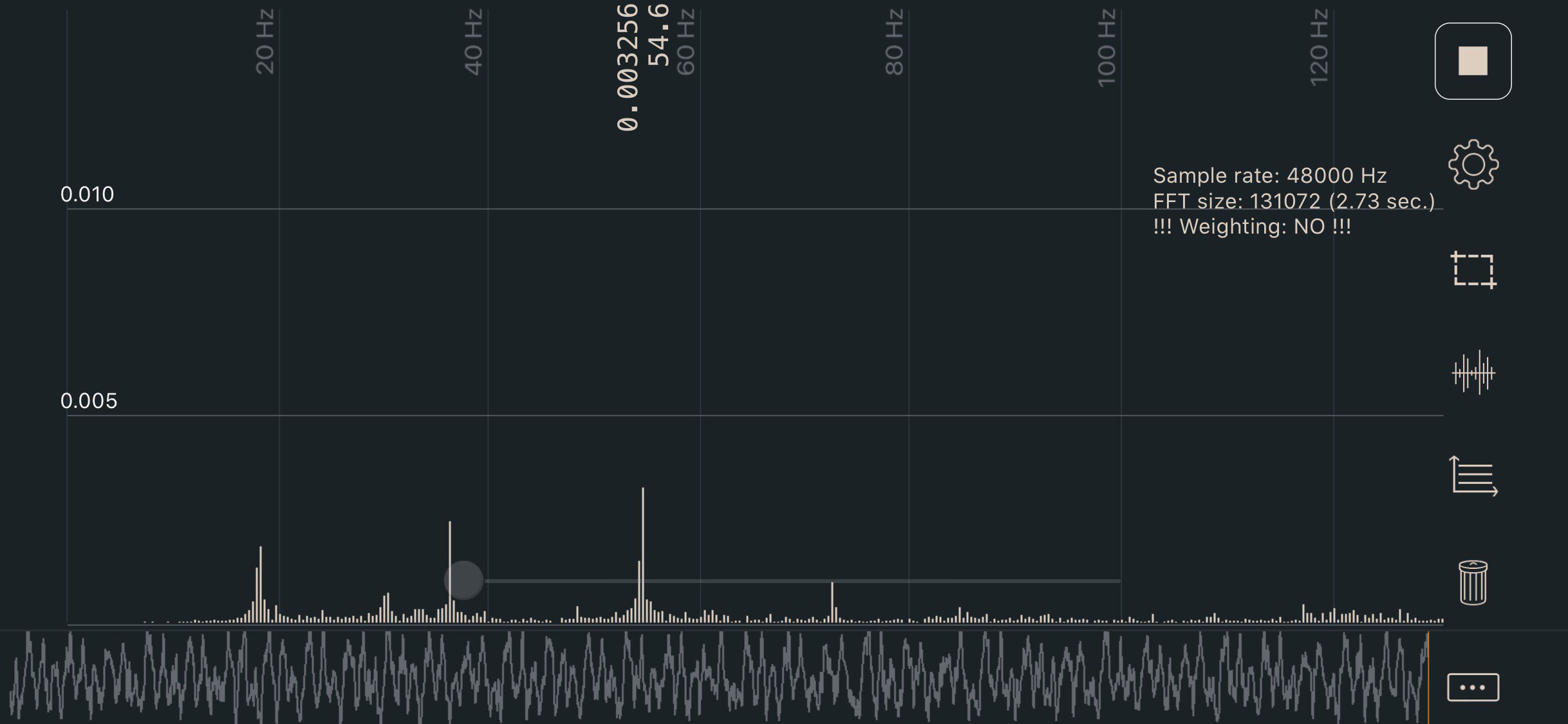
3. Adjust the tensions until the lowest frequency in your plot registers approximately 110Hz.
   * The A/B belt tensions can affect each other. Tightening one will also tighten the other. Go back and forth adjusting each until they are equal.
4. Move your X extrusion back at least a few centimeters and then back again. Re-check your tensions.

110hz equals roughly 2lb of belt tension here, which is on the lower end of the range. This should be a good starting point without stretching your belts too tight.

### Apps

* iOS: Sound Spectrum Analysis
* Android: Spectroid
* Both: Gates Carbon Drive *(use the “motorcycle” option)*
  * This app shows a single frequency rather than a graph. It’s more difficult to get a good reading, but easier to interpret the result.

### Sound Spectrum Analysis (iOS)

<figure><img src="/files/LiqUXdA1fETc7Y9ikYAZ" alt=""><figcaption></figcaption></figure>


# Maintenance Guide

**3D Printer Maintenance Guide**

Regular maintenance is key to ensuring your 3D printer operates at optimal performance. Below is a detailed guide with practical advice on routine inspections and consumable management.

**Routine Inspections**

1. **Hardware Check**
   * **Component Fastening:** Regularly inspect screws, rails, and brackets to ensure they are secure and not worn out, especially in high-vibration or high-temperature environments. Use tools like an Allen wrench to tighten any loose parts.
   * **Printed Part Inspection:** Look for signs of stress, such as discoloration, cracks, or deformation, particularly in 3D-printed components made from ABS or PLA, which can develop stress cracks over time.
2. **X-Carriage Check**
   * **Movement Stability:** Manually move the X-carriage to ensure smooth movement without any wobbling. If the carriage moves up and down, check whether the Quick Change Toolhead is secure and verify that the carriage is properly installed on the guide rails.
3. **PTFE Tube Check**
   * **Insertion Depth:** Ensure the PTFE tube is fully inserted into the hotend. If it is loose or retracting, inspect the extruder couplings for wear and check for friction or damage along the filament path.
4. **Hotend Stability**
   * **Hotend Security:** A loose hotend can cause inconsistent extrusion and affect print quality. For V6 hotends, ensure the heater block is firmly attached to the heat break to avoid heat transfer issues.
5. **Belt and Pulley Check**
   * **Belt Tension:** Periodically check the belt tension to ensure it is tight enough but not overly stretched. Over time, belts may stretch slightly, so use a tensioner to adjust as needed. If the problem persists, consider replacing the belts.
6. **Guide Rails and Lead Screw Maintenance**
   * **Cleaning and Lubrication:** Over time, dust and debris can mix with lubricant on the guide rails and lead screw, forming black grime. Regularly clean the carriage on the rails and the lead screw with a lint-free cloth or paper towel. Reapply lubricant to ensure smooth movement.
7. **Extruder Check**
   * **Debris Removal:** Filament residue and debris, especially from filled filaments like carbon fiber or wood, can accumulate in the extruder. Regularly clean the area to prevent clogging and inconsistent extrusion.
8. **Fan Check**
   * **Fan Speed:** Periodically inspect the cooling fans to ensure they are running at the correct speed. Fan speed affects cooling and print quality. Adjust the fan speed via manual control or software and ensure it operates properly at various temperatures. If you hear unusual noises or detect unstable speeds, replace the fan promptly.
9. **Lubrication**
   * **Frequency:** Lubricate the linear guide rails or ball screws after every few thousand hours of operation, using recommended lubricants. Oil-based lubricants may require more frequent reapplication, depending on usage.
10. **Consumable Replacements**

* **PTFE Tubes:** Replace PTFE tubes every 500-1000 hours of printing. Over time, the tube may wear down, affecting extrusion consistency and quality.
* **Nozzles and PEI Surface:** Check nozzle wear regularly, especially when printing with abrasive materials. Replace worn nozzles as needed to maintain print quality.

**Consumables Management**

1. **PTFE Tubes**
   * **Wear:** PTFE tubes degrade over time due to high temperatures and filament friction. Replacing them every 500 hours helps maintain consistent print quality, particularly for extended printing sessions.
2. **Nozzles**
   * **Wear and Clogging:** Brass nozzles wear faster when printing with filled materials like carbon fiber or metal powders. While PLA and ABS are gentler, if you experience uneven extrusion or clogging, it's time to replace the nozzle to avoid print failures.
3. **PEI Textured Plate**
   * **Adhesion Maintenance:** Our PEI textured surface may develop scratches and reduced adhesion over time. If adhesion issues arise, clean the surface with a detergent to remove debris and residue. Light sanding can restore adhesion and extend the plate’s lifespan.
4. **Fans**
   * **Spare Fans:** Cooling fans play a crucial role in printing. It is recommended to keep at least one spare fan on hand to handle potential failures. Fans are prone to wear, especially when printing high-temperature materials for extended periods.
5. **Spare Drivers and Thermistors**
   * **Drivers:** Stepper motor drivers may wear out or malfunction after extended use. Keep several spare drivers to ensure quick replacements when needed, avoiding printer downtime.
   * **Thermistors:** Thermistors are essential for controlling hotend and heated bed temperatures. Continuous use at high temperatures may cause thermistors to fail or lose accuracy. Keeping spare thermistors ensures that temperature control issues can be quickly addressed.
6. **Spare Parts Inventory**
   * **Stock and Shipping Time:** Given that some consumables have long shipping times, it’s advisable to stock a full set of essential parts and consumables (such as nozzles, PTFE tubes, belts, fans, drivers, and thermistors) to avoid downtime caused by the lack of replacement parts.

**Summary**

By regularly inspecting key components like guide rails, lead screws, and fans, and managing consumables effectively, you can extend the lifespan of your 3D printer, reduce downtime, and maintain consistent print quality.


# Product specs

## MKS Robin Nano V3.0 PIN Diagram

<figure><img src="/files/Lv4oOTW0DmCw728Aympz" alt=""><figcaption></figcaption></figure>

## Nema Motor

<figure><img src="/files/NCuMFMhWshWJV0e8eFV6" alt=""><figcaption></figcaption></figure>

<figure><img src="/files/BMKdAZT7X8yp9uz6qIhi" alt=""><figcaption></figcaption></figure>

## E**xtrusion**

<figure><img src="/files/ZDJHIapT7eT8OOwhCALU" alt=""><figcaption></figcaption></figure>

## **PRO Build Plate**

<figure><img src="/files/6PagSk3iBAJ38u6bIj1L" alt=""><figcaption></figcaption></figure>

## C**ables**

<figure><img src="/files/hwPznDFcWiZftbEIsLWj" alt=""><figcaption></figcaption></figure>

<figure><img src="/files/XgIyPLXP7Ed49jcGSsty" alt=""><figcaption></figcaption></figure>

<figure><img src="/files/taqysz7kyWFbZISDhbo5" alt=""><figcaption></figcaption></figure>

<figure><img src="/files/Rm7sSTDisbaQyXtg49HE" alt=""><figcaption></figcaption></figure>

## **Blower Fan**

<figure><img src="/files/jy7bZ0B5MvH5qxt3vAnp" alt=""><figcaption></figcaption></figure>


# ※SIBOOR TRIDENT \[JUNE]

SIBOOR Trident Overview

The SIBOOR Trident is an advanced 3D printer that stands out for its exceptional performance and precision. Here’s a detailed look at its key features and components:

**Key Features:**

* **Robust Metal Gantry:** Provides a stable and sturdy printing framework.
* **AWD Four-Wheel Drive:** Ensures smooth operation with a 9mm synchronous belt.
* **Reinforced X-Axis:** Utilizes a carbon fiber tube for added strength and rigidity.
* **Rapido 2.0 UHF Hotend:** Capable of reaching up to 320°C, with a flow rate up to 36 cubic millimeters per second, for high-performance printing.

**Performance:**

* **Acceleration:** Achieves up to 20,000 mm/s² for rapid and precise movements.
* **Printing Speed:** Delivers up to 800 mm/s for high-speed printing.

**Advanced Technology:**

* **Cartographer Eddy Current Sensor:** Generates a bed mesh in just 10 seconds, complemented by a 3Z full gantry leveling system for accurate calibration.
* **Stealthburner Extruder:** Supports high-performance printing with chamber temperatures up to 60°C.

**Electrical Components:**

* **MANTA M8P 2.0 Mainboard:** Provides robust control with a 350W high-power supply.
* **CB2 PI:** Features powerful processing capabilities, enhancing the printer’s overall performance.
* **TMC2240 Drivers:** Ensures smooth and quiet XY movements.
* **SB2209 RP2040 Tool Board:** Efficiently manages the hotend.

**Power Supply and Filtering:**

* **350W High-Power Supply:** Delivers reliable power for optimal performance.
* **Filtered Power Switch:** Provides additional protection and stability.

**Additional Mods:**

* **12032 Side-Blowing Fan:** Enhances part cooling and improves print quality.
* **ClickyClacky Door:** Aids in maintaining a clean and controlled environment.
* **FumePack Air Filtration Module:** Reduces airborne particles and maintains a healthier workspace.
* **Advanced Drive Cooling Solutions:** Ensures efficient cooling of drive components.

**Design Features:**

* **Inverted Electronics Compartment:** Facilitates easy maintenance with an accessible design.
* **HDMI Touchscreen:** Offers a high-definition interface for intuitive control.
* **MIC6 Aluminum Platform:** Features a black matte PRO print surface for superior build quality.

The SIBOOR Trident combines cutting-edge technology with high-speed performance, making it a premier choice for high-quality and reliable 3D printing.


# Bill of Materials

{% hint style="info" %}
**October 10, 2024**

* The electrical components of the SIBOOR Trident JUNE KIT are all installed on the base plate (based on our survey, the majority of users choose our default option). Therefore, we will no longer include DIN rails and SSR DIN brackets for free. If you need these accessories, please leave a note in your order, and we will provide them for free.

**August 25, 2024**

* The OOR-42STH48-2504A (S45) motor has been changed from a D-shaft to a round shaft.
* A Dupont to USB PCB board has been added for Cartographer firmware flashing.
* All fans now feature imported bearings and use multi-component motherboards.
* The 12032 blower, 5015 blower (fume pack), and 6020 fan now have shorter cables, with added adapter boards and extension cables.
* The PTFE tube has been upgraded from a 2mm ID × 4mm OD to a 3mm ID × 4mm OD
  {% endhint %}

{% embed url="<https://www.youtube.com/watch?embeds_referring_euri=https://cdn.iframe.ly/&source_ve_path=Mjg2NjQsMjg2NjY&v=hGUF4K53b7U>" %}

{% tabs %}
{% tab title="300 Model" %}

<table><thead><tr><th width="446">Part Description</th><th width="177">branding</th><th>Qty</th></tr></thead><tbody><tr><td>EVA Foam Tape 6mm Wide 3mm Thick ×5m</td><td>3M</td><td>2</td></tr><tr><td>EVA Foam Tape 6mm Wide 1mm Thick ×5m</td><td>3M</td><td>1</td></tr><tr><td>Hex Wrench Set</td><td>/</td><td>1</td></tr><tr><td>Telescopic 4CM Double-Ended Screwdriver</td><td>/</td><td>1</td></tr><tr><td>Black Cable Organizer Slot 25×25mm 365mm</td><td>/</td><td>5</td></tr><tr><td>Black Slot 6 Flat Strip 500mm</td><td>/</td><td>6</td></tr><tr><td>2020 Aluminum Profile Flat Anti-Slip Strip 500mm</td><td>/</td><td>4</td></tr><tr><td>Slot 6 Black U-Strip (Hard) 500mm</td><td>/</td><td>4</td></tr><tr><td>SIBOOR Trident Full Set of Fasteners</td><td>/</td><td>1</td></tr><tr><td>Euro Standard 20 Series M3</td><td>Nickel Plated</td><td>70</td></tr><tr><td>M3 Post-install T-nut</td><td>/</td><td>43</td></tr><tr><td>M5 Post-install T-nut</td><td>/</td><td>75</td></tr><tr><td>M3×4×5 Heat Insert Nut</td><td>/</td><td>78</td></tr><tr><td>M5 Flange Aluminum Alloy Lock Nut</td><td>/</td><td>7</td></tr><tr><td>M4 Hand Tighten Nut</td><td>Nickel Plated</td><td>3</td></tr><tr><td>M3×8 Nylon Column</td><td>/</td><td>4</td></tr><tr><td>5×45 Positioning Pin</td><td>/</td><td>4</td></tr><tr><td>M5×7×8 Brass Bushing</td><td>/</td><td>6</td></tr><tr><td>3×6mm Round Magnet</td><td>/</td><td>22</td></tr><tr><td>Black PC 4-01 Pneumatic Connector (Through)</td><td>/</td><td>1</td></tr><tr><td>GT2 20T Timing Pulley (5mm Bore, 9mm Wide)</td><td>SIBOOR</td><td>4</td></tr><tr><td>GT2 20T Idler Pulley (5mm Bore, 9mm Wide)</td><td>SIBOOR</td><td>2</td></tr><tr><td>F695ZZ Flanged Bearing</td><td>NSK</td><td>28</td></tr><tr><td>695ZZ Bearing</td><td>NSK</td><td>14</td></tr><tr><td>F623ZZ Flanged Bearing</td><td>NSK</td><td>2</td></tr><tr><td>GE5C Spherical Joint Bearing</td><td>/</td><td>3</td></tr><tr><td>BMG Extruder Assembly Kit (Red Reduction Wheel)</td><td>SIBOOR</td><td>1</td></tr><tr><td>Linear Rail MGN12H 350mm</td><td>SIBOOR</td><td>1</td></tr><tr><td>Linear Rail MGN9H 350mm</td><td>SIBOOR</td><td>2</td></tr><tr><td>Linear Rail MGN9H 300mm</td><td>SIBOOR</td><td>3</td></tr><tr><td>MGN12H 350mm Rail Fixing Aluminum Strip</td><td>SIBOOR</td><td>1</td></tr><tr><td>MGN9H 350mm Rail Fixing Aluminum Strip</td><td>SIBOOR</td><td>2</td></tr><tr><td>MGN9H 300mm Rail Fixing Aluminum Strip</td><td>SIBOOR</td><td>3</td></tr><tr><td>2MGT 9mm Wide Open Loop Timing Belt 2100mm</td><td>Gates</td><td>2</td></tr><tr><td>φ38×19mm Bore 6mm Cylindrical Rubber Foot</td><td>/</td><td>4</td></tr><tr><td>SIBOOR-42STH48-2504A (S45) Motor</td><td>SIBOOR</td><td>4</td></tr><tr><td>SIBOOR-14STH20-1004A Pancake Motor</td><td>SIBOOR</td><td>1</td></tr><tr><td>SIBOOR-1684A-300 Lead Screw Motor</td><td>SIBOOR</td><td>3</td></tr><tr><td>Cartographer V3 - Standard Version with ADXL345</td><td>Cartographer</td><td>1</td></tr><tr><td>Stealthburner SK6812-RGBW Light Strip</td><td>/</td><td>1</td></tr><tr><td>X-Axis Limit Switch</td><td>SIBOOR</td><td>1</td></tr><tr><td>Y-Axis Limit Switch</td><td>SIBOOR</td><td>1</td></tr><tr><td>Rapido Plus Hotend V2.0_ UHF [Black]</td><td>Phaetus</td><td>1</td></tr><tr><td>4010 Fan Ball Bearing 24V 8000RPM</td><td>SIBOOR</td><td>1</td></tr><tr><td>4010 Fan Twin Ball Bearing 24V 8000RPM</td><td>SIBOOR</td><td>1</td></tr><tr><td>5015 Blower Ball Bearing 24V 8000RPM</td><td>SIBOOR</td><td>1</td></tr><tr><td>5015 Blower Twin Ball Bearing 24V 8000RPM</td><td>SIBOOR</td><td>1</td></tr><tr><td>12032 Blower (24V) 3000RPM</td><td>SIBOOR</td><td>1</td></tr><tr><td>60×60×20 Fan Twin (24V) 5000RPM</td><td>SIBOOR</td><td>1</td></tr><tr><td>HDMI5 Touch Screen</td><td>Bigtreetech</td><td>1</td></tr><tr><td>MANTA M8P V2.0 Motherboard</td><td>Bigtreetech</td><td>1</td></tr><tr><td>TMC2240 Stepper Motor Driver</td><td>Bigtreetech</td><td>4</td></tr><tr><td>TMC2209 Stepper Motor Driver</td><td>Bigtreetech</td><td>3</td></tr><tr><td>EBB SB2209 (RP2040) CAN Board</td><td>Bigtreetech</td><td>1</td></tr><tr><td>(CM4102032) or (BTT PI CB2)</td><td>Raspberry Pi / BIQU</td><td>1</td></tr><tr><td>Relay Black Heat Sink 30×40×5mm (with Thermal Adhesive)</td><td></td><td>1</td></tr><tr><td>Three-Leg Filter Power Switch with Wire 10A</td><td>/</td><td>1</td></tr><tr><td>A-350FGF-24 Switching Power Supply</td><td>CHUANGLIAN</td><td>1</td></tr><tr><td>Delixi Relay CDG1-1DA 20A</td><td>DELIXI</td><td>1</td></tr><tr><td>Power Cord 3×1mm² 1.5m</td><td>/</td><td>1</td></tr><tr><td>2×4 White Teflon Tube (2m)</td><td>WHITE</td><td>2</td></tr><tr><td>Colorful Three-In Nine-Out Terminal Block</td><td>/</td><td>1</td></tr><tr><td>ctc90% Columnar Granules φ3.0mm Activated Carbon 200g</td><td>/</td><td>1</td></tr><tr><td>Black Nylon Cable Tie 4×150mm</td><td>/</td><td>40</td></tr><tr><td>SIBOOR Trident Full Set of Cables</td><td>/</td><td>1</td></tr><tr><td>6×10 Semi-Open Cable Drag Chain 42 Links</td><td>/</td><td>1</td></tr><tr><td>10×11 Openable Cable Drag Chain 24 Links</td><td>/</td><td>1</td></tr><tr><td>[B] Extrusion-2020-500-LCP-RCP-AV360</td><td>SIBOOR</td><td>4</td></tr><tr><td>[A] Extrusion-2020-420-TPW</td><td>SIBOOR</td><td>11</td></tr><tr><td>[C]F Extrusion-2020-420-AH210-TPW</td><td>SIBOOR</td><td>2</td></tr><tr><td>[H] Extrusion-2020-330-LTP</td><td>SIBOOR</td><td>1</td></tr><tr><td>[G] Extrusion-2020-282-LTP</td><td>SIBOOR</td><td>1</td></tr><tr><td>[D] Extrusion-2020-290</td><td>SIBOOR</td><td>1</td></tr><tr><td>[K] Extrusion-2020-500-LCH-RCH</td><td>SIBOOR</td><td>2</td></tr><tr><td>20×20 Carbon Tube 380mm Long</td><td>SIBOOR</td><td>1</td></tr><tr><td>Black Bakelite Deck - 419×419×4 mm</td><td>SIBOOR</td><td>1</td></tr><tr><td>Black Bakelite Base Plate - 437×437×4 mm</td><td>SIBOOR</td><td>1</td></tr><tr><td>Black Bakelite Back Plate - 432×472×4 mm</td><td>SIBOOR</td><td>1</td></tr><tr><td>Transparent PC Door Panel - 430×470×3 mm</td><td>SIBOOR</td><td>1</td></tr><tr><td>Transparent PC Side Panel - 433×473×3 mm</td><td>SIBOOR</td><td>2</td></tr><tr><td>Transparent PC Top Panel - 433×433×3 mm</td><td>SIBOOR</td><td>1</td></tr><tr><td>300x300mm Textured PRO Plate</td><td>SIBOOR</td><td>1</td></tr><tr><td>300×300×8mm MIC6 Aluminum Plate</td><td>SIBOOR</td><td>1</td></tr><tr><td>300×300mm 110V/220V 800W Heated Bed</td><td>SIBOOR</td><td>1</td></tr><tr><td>φ10×7.5mm ID 3.5 Bakelite Insulation Column</td><td>/</td><td>3</td></tr><tr><td>M3 Aluminum Alloy Washer</td><td>/</td><td>14</td></tr><tr><td>Metal CNC AWD Structural Parts</td><td>SIBOOR</td><td>1</td></tr><tr><td>Heated Bed Limit Metal Block</td><td>SIBOOR</td><td>2</td></tr><tr><td>ABS Supplemental Structural Parts</td><td>SIBOOR</td><td>1</td></tr><tr><td>ABS Decorative Parts for 300 Model(Optional)</td><td>SIBOOR</td><td>1</td></tr></tbody></table>
{% endtab %}

{% tab title="350 Model" %}

<table><thead><tr><th width="455">Part Description</th><th width="181">branding</th><th>Qty</th></tr></thead><tbody><tr><td>EVA Foam Tape 6mm Wide 3mm Thick ×5m</td><td>3M</td><td>2</td></tr><tr><td>EVA Foam Tape 6mm Wide 1mm Thick ×5m</td><td>3M</td><td>1</td></tr><tr><td>Hex Wrench Set</td><td>/</td><td>1</td></tr><tr><td>Telescopic 4CM Double-Ended Screwdriver</td><td>/</td><td>1</td></tr><tr><td>Black Cable Organizer Slot 25×25mm 365mm</td><td>/</td><td>5</td></tr><tr><td>Black Slot 6 Flat Strip 500mm</td><td>/</td><td>6</td></tr><tr><td>2020 Aluminum Profile Flat Anti-Slip Strip 500mm</td><td>/</td><td>4</td></tr><tr><td>Slot 6 Black U-Strip (Hard) 500mm</td><td>/</td><td>4</td></tr><tr><td>SIBOOR Trident Full Set of Fasteners</td><td>/</td><td>1</td></tr><tr><td>Euro Standard 20 Series M3</td><td>Nickel Plated</td><td>70</td></tr><tr><td>M3 Ball Nut</td><td>/</td><td>43</td></tr><tr><td>M5 Ball Nut</td><td>/</td><td>75</td></tr><tr><td>M3×4×5 Heat Insert Nut</td><td>/</td><td>78</td></tr><tr><td>M5 Flange Aluminum Alloy Lock Nut</td><td>/</td><td>7</td></tr><tr><td>M4 Hand Tighten Nut</td><td>Nickel Plated</td><td>3</td></tr><tr><td>M3×8 Nylon Column</td><td>/</td><td>4</td></tr><tr><td>5×45 Positioning Pin</td><td>/</td><td>4</td></tr><tr><td>M5×7×8 Brass Bushing</td><td>/</td><td>6</td></tr><tr><td>3×6mm Round Magnet</td><td>/</td><td>22</td></tr><tr><td>Black PC 4-01 Pneumatic Connector (Through)</td><td>/</td><td>1</td></tr><tr><td>GT2 20T Timing Pulley (5mm Bore, 9mm Wide)</td><td>SIBOOR</td><td>4</td></tr><tr><td>GT2 20T Idler Pulley (5mm Bore, 9mm Wide)</td><td>SIBOOR</td><td>2</td></tr><tr><td>F695ZZ Flanged Bearing</td><td>NSK</td><td>28</td></tr><tr><td>695ZZ Bearing</td><td>NSK</td><td>14</td></tr><tr><td>F623ZZ Flanged Bearing</td><td>NSK</td><td>2</td></tr><tr><td>GE5C Spherical Joint Bearing</td><td>/</td><td>3</td></tr><tr><td>BMG Extruder Assembly Kit (Red Reduction Wheel)</td><td>SIBOOR</td><td>1</td></tr><tr><td>Linear Rail MGN12H 400mm</td><td>SIBOOR</td><td>1</td></tr><tr><td>Linear Rail MGN9H 400mm</td><td>SIBOOR</td><td>2</td></tr><tr><td>Linear Rail MGN9H 300mm</td><td>SIBOOR</td><td>3</td></tr><tr><td>MGN9H 400mm Rail Fixing Aluminum Strip</td><td>SIBOOR</td><td>1</td></tr><tr><td>MGN9H 350mm Rail Fixing Aluminum Strip</td><td>SIBOOR</td><td>2</td></tr><tr><td>MGN9H 300mm Rail Fixing Aluminum Strip</td><td>SIBOOR</td><td>3</td></tr><tr><td>2MGT 9mm Wide Open Loop Timing Belt 2300mm</td><td>Gates</td><td>2</td></tr><tr><td>φ38×19mm Bore 6mm Cylindrical Rubber Foot</td><td>/</td><td>4</td></tr><tr><td>SIBOOR-42STH48-2504A (S45) Motor</td><td>SIBOOR</td><td>4</td></tr><tr><td>SIBOOR-14STH20-1004A Pancake Motor</td><td>SIBOOR</td><td>1</td></tr><tr><td>SIBOOR-1684A-300 Lead Screw Motor</td><td>SIBOOR</td><td>3</td></tr><tr><td>Cartographer V3 - Standard Version with ADXL345</td><td>Cartographer</td><td>1</td></tr><tr><td>Stealthburner SK6812-RGBW Light Strip</td><td>/</td><td>1</td></tr><tr><td>X-Axis Limit Switch</td><td>SIBOOR</td><td>1</td></tr><tr><td>Y-Axis Limit Switch</td><td>SIBOOR</td><td>1</td></tr><tr><td>RapiRapido Plus Hotend V2.0_ UHF [Black]</td><td>Phaetus</td><td>1</td></tr><tr><td>4010 Fan Ball Bearing 24V 8000RPM</td><td>SIBOOR</td><td>1</td></tr><tr><td>4010 Fan Twin Ball Bearing 24V 8000RPM</td><td>SIBOOR</td><td>1</td></tr><tr><td>5015 Blower Ball Bearing 24V 8000RPM</td><td>SIBOOR</td><td>1</td></tr><tr><td>5015 Blower Twin Ball Bearing 24V 8000RPM</td><td>SIBOOR</td><td>1</td></tr><tr><td>12032 Blower (24V) 3000RPM</td><td>SIBOOR</td><td>1</td></tr><tr><td>60×60×20 Fan Twin (24V) 5000RPM</td><td>SIBOOR</td><td>1</td></tr><tr><td>HDMI5 Touch Screen</td><td>Bigtreetech</td><td>1</td></tr><tr><td>MANTA M8P V2.0 Motherboard</td><td>Bigtreetech</td><td>1</td></tr><tr><td>TMC2240 Stepper Motor Driver</td><td>Bigtreetech</td><td>4</td></tr><tr><td>TMC2209 Stepper Motor Driver</td><td>Bigtreetech</td><td>3</td></tr><tr><td>EBB SB2209 (RP2040) CAN Board</td><td>Bigtreetech</td><td>1</td></tr><tr><td>(CM4102032) or (BTT PI CB2)</td><td>Raspberry Pi / BIQU</td><td>1</td></tr><tr><td>Relay Black Heat Sink 30×40×5mm (with Thermal Adhesive)</td><td></td><td>1</td></tr><tr><td>Three-Leg Filter Power Switch with Wire 10A</td><td>/</td><td>1</td></tr><tr><td>A-350FGF-24 Switching Power Supply</td><td>CHUANGLIAN</td><td>1</td></tr><tr><td>Delixi Relay CDG1-1DA 20A</td><td>DELIXI</td><td>1</td></tr><tr><td>Power Cord 3×1mm² 1.5m</td><td>/</td><td>1</td></tr><tr><td>2×4 White Teflon Tube (2m)</td><td>WHITE</td><td>2</td></tr><tr><td>Colorful Three-In Nine-Out Terminal Block</td><td>/</td><td>1</td></tr><tr><td>ctc90% Columnar Granules φ3.0mm Activated Carbon 200g</td><td>/</td><td>1</td></tr><tr><td>Black Nylon Cable Tie 4×150mm</td><td>/</td><td>40</td></tr><tr><td>SIBOOR Trident Full Set of Cables</td><td>/</td><td>1</td></tr><tr><td>6×10 Semi-Open Cable Drag Chain 47 Links</td><td>/</td><td>1</td></tr><tr><td>10×11 Openable Cable Drag Chain 24 Links</td><td>/</td><td>1</td></tr><tr><td>[B] Extrusion-2020-500-LCP-RCP-AV360</td><td>SIBOOR</td><td>4</td></tr><tr><td>[A] Extrusion-2020-470-TPW</td><td>SIBOOR</td><td>11</td></tr><tr><td>[CF] Extrusion-2020-470-AH235-TPW</td><td>SIBOOR</td><td>1</td></tr><tr><td>[H] Extrusion-2020-330-LTP</td><td>SIBOOR</td><td>1</td></tr><tr><td>[G] Extrusion-2020-332-LTP</td><td>SIBOOR</td><td>1</td></tr><tr><td>[D] Extrusion-2020-340</td><td>SIBOOR</td><td>1</td></tr><tr><td>[K] Extrusion-2020-500-LCH-RCH</td><td>SIBOOR</td><td>2</td></tr><tr><td>20×20 Carbon Tube 430mm Long</td><td>SIBOOR</td><td>1</td></tr><tr><td>Black Bakelite Deck - 469×469×4 mm</td><td>SIBOOR</td><td>1</td></tr><tr><td>Black Bakelite Base Plate - 487×487×4 mm</td><td>SIBOOR</td><td>1</td></tr><tr><td>Black Bakelite Back Plate - 482×472×4 mm</td><td>SIBOOR</td><td>1</td></tr><tr><td>Transparent PC Door Panel - 480×470×3 mm</td><td>SIBOOR</td><td>1</td></tr><tr><td>Transparent PC Side Panel - 483×473×3 mm</td><td>SIBOOR</td><td>2</td></tr><tr><td>Transparent PC Top Panel - 483×483×3 mm</td><td>SIBOOR</td><td>1</td></tr><tr><td>350x350mm Textured PRO Plate</td><td>SIBOOR</td><td>1</td></tr><tr><td>300×350×8mm MIC6 Aluminum Plate</td><td>SIBOOR</td><td>1</td></tr><tr><td>350×350mm 110V/220V 1000W Heated Bed</td><td>SIBOOR</td><td>1</td></tr><tr><td>φ10×7.5mm ID 3.5 Bakelite Insulation Column</td><td>/</td><td>3</td></tr><tr><td>M3 Aluminum Alloy Washer</td><td>/</td><td>14</td></tr><tr><td>Metal CNC AWD Structural Parts</td><td>SIBOOR</td><td>1</td></tr><tr><td>Heated Bed Limit Metal Block</td><td>SIBOOR</td><td>2</td></tr><tr><td>ABS Supplemental Structural Parts</td><td>SIBOOR</td><td>1</td></tr><tr><td>ABS Decorative Parts for 350 Model(Optional)</td><td>SIBOOR</td><td>1</td></tr></tbody></table>
{% endtab %}
{% endtabs %}


# The Build


# Printed Parts（Oct/17）

## ※Printed Parts Guideline

The Voron Team has provided the following print guidelines for you to follow in order to have the best chance at success with your parts. There are often questions about substituting materials or changing printing standards, but we recommend you follow these.

| Setting                 | Recommendation                             |
| ----------------------- | ------------------------------------------ |
| 3D Printing Process     | Fused Deposition Modeling (FDM)            |
| Material                | ABS                                        |
| Infill Type             | Grid, Gyroid, Honeycomb, Triangle or Cubic |
| Layer Height            | 0.2mm                                      |
| Wall Count              | 4                                          |
| Extrusion Width         | Forced 0.4mm                               |
| Solid Top/Bottom layers | 5                                          |

### ※Download STL files

{% embed url="<https://github.com/Lzhikai/SIBOOR-Voron-Trident-June/tree/main/STL>" %}

### ※FILE NAMING

By this time, you should have already downloaded our STL files from the Voron GitHub. You might have noticed that we use a unique naming convention for the files. Here's how to interpret them:

{% hint style="info" %}
**PRIMARY COLOR**\
Example: `z_joint_lower_x4.stl`\
These files will have no special identifier at the start of the filename.

***

**ACCENT COLOR**\
Example: `[a]_tensioner_left.stl`\
We add “\[a]” to the front of any STL file intended to be printed with accent color.

***

**QUANTITY REQUIRED**\
Example: `[a]_z_belt_clip_lower_x4.stl`\
If a file ends with “\_x#”, it indicates the quantity of that part required to build the machine.

***

**OPAQUE COLOR**\
Example: `[o]_stealthburner_LED_diffuser_mask.stl`\
The “\[o]” prefix indicates that the file should be printed using opaque filament.

***

**TRANSLUCENT COLOR**\
Example: `[c]_stealthburner_LED_diffuser_cut_2.stl`\
The “\[c]” prefix indicates that the file should be printed using translucent filament.

***

**ADDITIONAL NOTES**

* The suffix "**by\_SIBOOR**" on some STL files indicates that these files differ from the original VORON design or the original MOD design and are specifically tailored for the **SIBOOR KIT**.
* The prefix "**\[Two-color]**" indicates that the STL file requires printing with two different colors of ABS filament.

***

{% endhint %}

### ※Change Log

{% hint style="info" %}
The modification history of the STL files by SIBOOR since their release will be documented here.

2024/10/17

* **Skirt/【HDMI5\_Display\_Bracket\_by\_SIBOOR】** - Modification\
  Adjusted the dimensions to avoid interference with the left and right skirt mesh.
* **Stealthburner/【Distal\_end\_of\_drag\_chain\_bracket\_by\_SIBOOR】** - Modification\
  Reversed the drag chain mounting position and modified the mounting hole locations, making it easier to remove and adjust, while also enhancing the appearance.
* **Z\_Assembly/【z\_stepper\_rear】** - Modification\
  Added a wiring groove for the fume pack to ensure a tidier and more aesthetically pleasing wiring.
* **Other/【Skirt\_Fan\_Adapter\_PCB\_Bracket】** - Added\
  Facilitates skirt fan cable management and removal.
* **Other/【X\_Carbon\_Tube\_Fixings\_FLANGE\_NUT】** - Added\
  For fixing the X carbon tube, making assembly more convenient.
  {% endhint %}

### ※Essential\_\_Functional\_Parts

<figure><img src="/files/VpHTTFcTbGsR2LywRe6f" alt=""><figcaption></figcaption></figure>

### ※Non-essential\_Functional\_Parts

<figure><img src="/files/j8tSJmKtFCtYsVCknpVV" alt=""><figcaption></figcaption></figure>


# Assembly manual

## ※Wiring diagram

{% hint style="warning" %}
The latest version of the wiring diagram is placed here. Please refer to the most recent release for wiring.

**2024/8/16 Revision:**&#x20;

Move the voltage jumper caps for the 3 Z-axes to Vin, so they default to using the motherboard voltage. This adjustment is to prevent users from accidentally damaging TMC2209 drivers, which only operate at 24V, when upgrading the XY drivers to 48V.
{% endhint %}

<figure><img src="/files/M8uLH8ZgkXOH2fKL7NR2" alt=""><figcaption></figcaption></figure>

## ※Assembly manual&#x20;

{% file src="/files/TR64sXQDzRSovxc1pnth" %}

{% hint style="warning" %}
**2024/12/31 Revision:**&#x20;

* Added the installation diagram for the **fan adapter board** and **extension cable**.
* Added the installation diagram for the **flange nut fasteners** on both sides of the **carbon tube**.
* Updated the installation diagram for the **remote end fasteners** of the **drag chain**.
* Additionally, some **minor details** have been updated.

**Important Note:**&#x20;

This assembly manual is exclusively designed for the SIBOOR Trident JUNE kit. For the official VORON Trident assembly manual, please refer to the following link: [https://github.com/VoronDesign/Voron-Trident/tree/main/Manual ](<https://github.com/VoronDesign/Voron-Trident/tree/main/Manual >)
{% endhint %}

{% hint style="success" %}
**Why the Change?**\
The SIBOOR Trident JUNE kit includes numerous modifications and significant electrical adjustments, making it insufficient to simply add supplementary pages to the existing manual. Navigating through many pages repeatedly would be cumbersome. To enhance the user experience, SIBOOR has decided to create a new assembly guide from scratch, ensuring it aligns closely with the Trident JUNE kit.&#x20;

The assembly logic and the presentation of most steps in this manual are inspired by the original VORON manual.

If you find an issue in the documentation or have a suggestion for improvement, please consider opening an issue on GitHub&#x20;

(<https://github.com/Lzhikai/SIBOOR-Voron-Trident-June/issues>). When raising an issue, include the relevant page numbers and a brief description; annotated screenshots are also highly appreciated. We periodically update the manual based on feedback.
{% endhint %}

<figure><img src="/files/ZXkcLIGe58fuc9pgmVFI" alt=""><figcaption></figcaption></figure>

## ※Assembly video

This assembly video for the SIBOOR TRINDET JUNE kit, created by our partner EKO 3D, will help you better understand the assembly steps and process. Special thanks to David for his dedicated efforts!

{% embed url="<https://youtu.be/KXr87Xk99JA>" %}


# Initial Startup（Dec/05）

### ※Check Wiring

Before powering on, perform a final check of all connections:

* 110/220V wiring section
* 5V/24V wiring section
* Ensure all jumpers are inserted in the correct positions
* Verify all drivers are inserted into the appropriate driver slots and properly seated

<figure><img src="/files/M8uLH8ZgkXOH2fKL7NR2" alt=""><figcaption></figcaption></figure>

{% hint style="danger" %}
Even with professional expertise, please do not skip the inspection steps, as this could lead to the following issues, potentially causing irreversible damage:

* **110/220V Short Circuit:** The circuit breaker for the power supply area (e.g., in an office) will trip immediately.
* **24V Short Circuit:** The printer will fail to start, and the 24V power supply will enter automatic protection mode.
* **Mainboard 5V Short Circuit:** The mainboard MCU will be damaged.
* **Hotend Toolboard 5V Short Circuit:** The MCU, 5V power supply module, and Cartographer will be damaged."
  {% endhint %}

{% hint style="info" %}
**2024/8/16:** The voltage jumper caps for Z0/Z1/Z2 have been adjusted to VIN of the mainboard. This modification is intended to prevent damage to the three TMC2209 drivers on the Z-axis when users upgrade the XY axis to 48V.
{% endhint %}

***

### ※Connect to the Network.

Plug in the power cable and press the switch. If all the cables are connected correctly, the display screen will light up shortly.

After powering on, the display should light up. Follow the image instructions to connect to the network.

<figure><img src="/files/JB7yuWv0pmFZY42vajMO" alt=""><figcaption><p>Diagram of connecting a display screen to the network</p></figcaption></figure>

### ※Upload the CFG file.

In your browser, enter the IP address obtained in the previous step and press Enter to access the Trident Web Control Interface.

<figure><img src="/files/7d6Q6B3ucc5xk0qpivQe" alt=""><figcaption><p>Log in to the printer's backend via the browser</p></figcaption></figure>

Due to the absence of the correct CFG configuration file, the system will encounter an error. Please download the appropriate `Printer.cfg` configuration file, upload it, and then rename the uploaded file to `printer.cfg`.

<figure><img src="/files/TDAkSumsjH1fW18Ac8Lt" alt=""><figcaption><p>System error due to the missing <code>printer.cfg</code> file</p></figcaption></figure>

<table><thead><tr><th data-type="files">Trident  AWD 300 Model </th><th data-type="files">Trident 2WD 300 Model </th></tr></thead><tbody><tr><td><a href="/files/SzSGrFT4i31RWY05OUR1">/files/SzSGrFT4i31RWY05OUR1</a></td><td><a href="/files/naZ5mC7R7JgUJlseDWxO">/files/naZ5mC7R7JgUJlseDWxO</a></td></tr><tr><td><a href="/files/lAkPNQolD9aaF3j4Heff">/files/lAkPNQolD9aaF3j4Heff</a></td><td><a href="/files/rpBCRbEvhxLxakCVPOFH">/files/rpBCRbEvhxLxakCVPOFH</a></td></tr><tr><td></td><td></td></tr></tbody></table>

<table><thead><tr><th data-type="files">Trident AWD 350 Model </th><th data-type="files">Trident 2WD 350 Model </th></tr></thead><tbody><tr><td><a href="/files/Nn3jsLuGM8UkYyu71UdC">/files/Nn3jsLuGM8UkYyu71UdC</a></td><td><a href="/files/tsQjqpa9Cc0dQlEtMQdy">/files/tsQjqpa9Cc0dQlEtMQdy</a></td></tr><tr><td><a href="/files/DfnNYnWf6RRFmPUUYcuI">/files/DfnNYnWf6RRFmPUUYcuI</a></td><td><a href="/files/aNbCvzxsgIkmUKKKsiwb">/files/aNbCvzxsgIkmUKKKsiwb</a></td></tr><tr><td></td><td></td></tr></tbody></table>

{% hint style="info" %}
**2024/12/05 Revised**

Fixed the pin assignment error for \[controller\_fan] and \[driver\_fan].\
Changed from `PF8` to `PF6`.

**2024/11/26 Revised**

Removed the LED macros and content related to heat soak from the \[gcode\_macro PRINT\_START].

<mark style="color:red;">**2024/10/29 Revised （important）**</mark>

Update the Cartographer Probe configuration to the latest version, with Survey Touch set as the default mode.

If you encounter the error: **"Unknown pin chip name 'probe'"**, please refer to this tutorial: [Cartographer to Survey Touch Mode](https://docs.siboor.com/siboor-trident-june/faq-oct-17/new-cartographer-to-survey-touch-mode).

Use an SSH tool to update the Cartographer software to version 5.0.0 and flash the latest firmware to the Cartographer Probe. (You can skip the section at the end of the tutorial regarding modifications to the `.cfg` file.)

**2024/9/21 Revised**

Removed the `SAVE_CONFIG` section at the end. In the previous configuration, due to formatting issues, the newly saved calibration data could not be properly applied. Even after calibrating the cartographer model, the Z-axis could not home correctly.&#x20;

Additionally, the extruder motor direction has been reversed.

**2024/9/13 Revised**

Due to the use of multi-component motors in the fans of the second batch of kits, the cycle time for all fan configurations has been updated to 0.00003

**2024/8/24 Revised**

Added code lines to redefine the M106 command so that FAN0/FAN2/FAN3 can be properly controlled within the slicing software. Also, added code to turn off the part cooling fan, additional part cooling fan, and filter fan in the print end and cancel print macros.

{% endhint %}

***

<figure><img src="/files/AzOymjZJFiwXFLwmEWhl" alt=""><figcaption><p>Upload the correct <code>printer.cfg</code> file and rename it</p></figcaption></figure>

### ※Enter the UUID

After restarting, if the system still prompts an error about being unable to read the UUID, it’s because each CAN device in a Trident June kit has a unique UUID. Therefore, you need to obtain the correct UUID and enter it in the appropriate place in the `printer.cfg` file.

<figure><img src="/files/zPYwAXex6tC6xryozSxG" alt=""><figcaption></figcaption></figure>

In the Trident June kit, there are a total of three CAN devices: the MANTA M8P board, the EBB 2209 RP2040 CAN hotend toolboard, and the Cartographer V3 inductive leveling sensor.

<figure><img src="/files/SO6aRdvVqjZFlaBDOW8m" alt=""><figcaption><p>CAN Communication Link Diagram</p></figcaption></figure>

Disconnect the cable connector indicated by the red circle in the image below; at this point, only the mainboard will have CAN communication

<figure><img src="/files/zIQ5EwXVoDzFrnaFybSn" alt=""><figcaption><p>Disconnect the EBB 2209 RP2040 CAN and Cartographer V3 connections</p></figcaption></figure>

Double-click to enter `Printer.cfg`, click the `DEVICES` button in the upper right corner, and then click `Refresh`. At this point, you will obtain the UUID of the mainboard.

<figure><img src="/files/wri5OTxSokHF9wSAZcy0" alt=""><figcaption><p>Read the UUID of the MANTA M8P board</p></figcaption></figure>

Find the configuration line for `[mcu]`, and paste the copied UUID into the corresponding field. After completing the entry, click `SAVE & RESTART` in the upper right corner.

```
[mcu] 
canbus_uuid: 41cbab4642d7 
```

<figure><img src="/files/5FCLwD5YWznlcIbSavAt" alt=""><figcaption><p>Enter the UUID of the MANTA M8P board</p></figcaption></figure>

Since the UUIDs for the two remaining CAN devices have not been entered, there will still be an error after restarting. At this point, connect the MANTA M8P board and the EBB 2209 RP2040 CAN hotend toolboard with their respective cables.

<figure><img src="/files/SlcMsArkgHUkmja0xQxg" alt=""><figcaption><p>Connect the MANTA M8P board and the EBB 2209 RP2040 CAN</p></figcaption></figure>

Re-enter `printer.cfg` and use the device function in the upper right corner to refresh the UUID. Since the correctly connected CAN `DEVICES` will not be read again, the UUID at this point comes from the EBB 2209 RP2040 CAN hotend toolboard. Enter this UUID in the appropriate location.

{% hint style="warning" %}
`Note: If the UUID of the MANTA M8P board has not disappeared, you can ignore it and only use the second UUID that appears after refreshing.`
{% endhint %}

```
[mcu EBBCan]
canbus_uuid: 2733cea0ce24
```

<figure><img src="/files/iXapuWd6vMIrG5XJYWqQ" alt=""><figcaption><p>Read and enter the UUID of the EBB 2209 RP2040 CAN</p></figcaption></figure>

After the restart is complete, connect the EBB 2209 RP2040 CAN hotend toolboard and Cartographer V3 inductive leveling sensor with their respective cables.

<figure><img src="/files/msSb1AHq913jiKkr2H1W" alt=""><figcaption><p>Connect the EBB 2209 RP2040 CAN and Cartographer V3</p></figcaption></figure>

Re-enter `printer.cfg` and use the device function in the upper right corner to refresh the UUID. Since the correctly connected CAN devices will not be read again, the UUID at this point comes from the Cartographer V3. Enter this UUID in the appropriate location.

```
[scanner]
canbus_uuid: da9011b7aec6
```

<figure><img src="/files/n7s5fHAuylBfEYfzMCJi" alt=""><figcaption><p>Read and enter the UUID of the Cartographer V3</p></figcaption></figure>


# Initial Startup Checks\[Nov/28]

点击查看需要覆盖的点击查看※Verify Temperature

Start by verifying that temperatures are being properly reported. Navigate to the Mainsail temperature graph.

<figure><img src="/files/0ww36M8GYCAHNraIL6C8" alt=""><figcaption></figcaption></figure>

Verify that the nozzle and bed temperatures are displaying correctly and are not increasing. If the temperatures continue to rise, disconnect the printer from power. If the temperatures are inaccurate, the issue may be due to wiring or hardware faults.

### ※Verify heaters <a href="#verify-heaters" id="verify-heaters"></a>

Navigate to the temperature graph and type in 50 followed by enter in the “Tool” temperature target field. The extruder temperature in the graph should start to increase (within about 10 seconds or so). Then go to the “Tool” temperature drop-down box and select “Off”. After several minutes the temperature should start to return to its initial room temperature value. If the temperature does not increase, Please check the wiring.

{% hint style="danger" %}
**Nozzle Preload and Filament Leakage Notice**

During the initial setup of your Rapido 2.0 hotend, please be aware that some nozzles may have insufficient preload, which can cause filament leakage during printing. To prevent this, it is recommended to retighten the nozzle after the first heating of the hotend.

The kit includes two nozzles: a 0.4mm copper-plated (silver) nozzle and a pre-installed 0.6mm hardened steel nozzle. Ensure that you configure the correct nozzle diameter in both the printer.cfg file and your slicing software. Incorrect settings may result in under-extrusion or over-extrusion.
{% endhint %}

Perform the above steps again with the bed.

### ※Check Motor Operation

To verify that each stepper motor is operating correctly, send the following command in the terminal:

`STEPPER_BUZZ STEPPER=stepper_x`

The STEPPER\_BUZZ command will cause the given stepper to move one millimeter in a positive direction and then it will return to its starting position. It will perform this oscillation ten times. we will verify direction again later, ideally all motors will be running correctly at the end of this test. See the list below for the expected motion for each command.

Note, if you have trouble seeing what direction a motor is rotating, try adding a small sharpy mark on the pulley. clockwise and counterclockwise are from the top down view looking at the X and Y motors.

<figure><img src="/files/MPWZHVxEr5x6wwgAqaD1" alt=""><figcaption></figcaption></figure>

Run this command for each of the motors:

<table><thead><tr><th width="165"></th><th></th></tr></thead><tbody><tr><td>stepper_x</td><td>The motor will rotate counterclockwise first, then back clockwise.</td></tr><tr><td>stepper_y</td><td>The motor will rotate counterclockwise first, then back clockwise.</td></tr><tr><td>stepper_x1</td><td>The motor will rotate counterclockwise first, then back clockwise.</td></tr><tr><td>stepper_y1</td><td>The motor will rotate counterclockwise first, then back clockwise.</td></tr><tr><td>stepper_z</td><td>The front left corner of the bed moves down, then back up.</td></tr><tr><td>stepper_z1</td><td>The back of the bed moves down, then back up.</td></tr><tr><td>stepper_z2</td><td>The front right corner of the bed moves down, then back up.</td></tr><tr><td>extruder</td><td>Movement: Direction will be tested later.</td></tr></tbody></table>

If the specified motor is not turning, please check the wiring and ensure that it is connected to the correct port.

### ※XY Endstop Check <a href="#endstop-check" id="endstop-check"></a>

Make sure that none of the X, Y endstops are being pressed. Then send a `QUERY_ENDSTOPS` command. The terminal window should respond with the following:

```
Send: QUERY_ENDSTOPS
Recv: x:open y:open z:triggered
```

If any of them say “triggered” instead of “open”, double-check to make sure none of them are pressed. Next, manually press the X endstop switch, send the `QUERY_ENDSTOPS` command again, and make sure that the X endstop says “triggered and the Y s stay open. Repeat with the Y  endstops.

If it is found that one of the endstops has inverted logic (i.e. it reads as “open” when it is pressed and “triggered” when not pressed), Check if the Endstop is properly installed, the cables are secure and not damaged, and if they are connected to the correct port.

### ※XY Homing Check <a href="#xy-homing-check" id="xy-homing-check"></a>

At this point everything is ready to home X and Y.

**Important:** You need to be able to quickly stop the printer in case something goes wrong (e.g. the tool head goes the wrong direction). There are a few ways of doing this:

1. There is a red emergency stop icon in the lower left corner of the display. Click on it to see what happens—Klipper should shut down, but the Raspberry Pi and Mainsail should remain running, although disconnected from Klipper. Press "Connect" in the upper left corner of Mainsail, then send a `FIRMWARE_RESTART` command in the Mainsail terminal window to reboot the printer and get it running again.
2. Have a computer right next to the printer with the `RESTART` or `M112` command already in the terminal command line in Mainsail. When you start homing the printer, if it goes in the wrong direction, quickly send the restart command and it will stop the printer.
3. As a “nuclear” option, power off the printer with the power switch if something goes wrong. This is not ideal because it may corrupt the files on the SD card and to recover would require reinstalling everything from scratch.

Once you have a testing procedure for stopping the printer in case of an issue, you can proceed to test the X and Y movements. Note: You need to test both X and Y to accurately determine what adjustments are necessary. First, send a `G28 Y` command. This will home the Y-axis only: the tool head should move to the back of the printer until it hits the Y endstop. Next, test the X-axis by sending a `G28 X` command; the tool head should move to the right.

{% hint style="info" %}
**Why move the Y-axis before the X-axis?**\
Due to the AWD structure, the platform loses a portion of the area at the front on both sides. If the tool head home  while near the front, it may collide with the motor.

**Not moving in the expected direction?**&#x20;

Check that the XY motor cable and extension cable wire sequence are consistent, check that the extension cable is plugged into the port of the MANTA M8P and that the wire sequence is in the same order as shown in the wiring diagram, if not, adjust the wire sequence.

**Not only is it not moving in the expected direction, but it is also making a strong noise and shaking?**&#x20;

Repeat the Check Motor Operation procedure to ensure that all motors are turning in the direction shown in the documentation.
{% endhint %}

### ※Check Fan

{% hint style="warning" %}
Note: If you are from the first batch of pre-sales or if your shipment was before August 29, 2024, please update your configuration. Copy the following settings and overwrite the existing fan configuration in `printer.cfg` before testing.
{% endhint %}

<details>

<summary>Click to see the configurations that need to be overridden</summary>

```
#####################################################################
##                  Fans
#####################################################################

[heater_fan hotend_fan]          # Hotend fan
pin: EBBCan:gpio14               # Hotend fan pin
heater: extruder                 # Associated heating device
heater_temp: 50.0                # Temperature to start the fan
cycle_time: 0.01                 # Cycle time

#--------------------------------------------------------------------

[heater_fan Skirt_fan]            # Skirt fan 
pin: PF9                         # FAN-2
cycle_time: 0.00003              # Cycle time
shutdown_speed: 0.0              # Closing speed (Please do not change)
kick_start_time: 0.5             # start-up time (Please do not change)
heater: heater_bed               # Related equipment: heater_bed
heater_temp: 50                  # How many degrees does the heat bed reach to activate the fan
fan_speed: 0.5                   # Fan speed

#--------------------------------------------------------------------

[controller_fan driver_fan]      # Driver cooling fan
pin: PF8                         # Fan pin 
cycle_time: 0.01                 # Cycle time
max_power: 1.0                   # Maximum power
shutdown_speed: 0.0              # Shutdown speed
fan_speed: 0.8                   # Fan speed when heater or stepper driver is active (0.0 to 1.0). Default is 1.0.
idle_timeout: 90                 # Time in seconds to keep the fan running after the stepper driver or heater is no longer active. Default is 30 seconds.
idle_speed: 0.4                  # Fan speed after the stepper driver is no longer active and before idle_timeout is reached (0.0 to 1.0). Default is fan_speed.
stepper: stepper_x               # Active motors
#Define the name of the heater/stepper configuration section associated with this fan. 
#If a comma-separated list of heater/stepper names is provided here, the fan will be enabled when any of the given heaters/steppers are enabled.
#The default heater is "extruder", and the default stepper is all steppers.

#--------------------------------------------------------------------

#Note: The following FAN0/FAN1/FAN2 settings are only applicable when using OrcaSlicer,
#as only OrcaSlicer allows for the additional configuration of parts cooling fans and filter fans. 
#If you use other slicing software, please comment out the following configurations.
# instead of using [fan], we define the default part cooling fan with [fan_generic] here
# this is the default part cooling fan

[fan_generic fan0]               # 5015 Part cooling Blower 
pin: EBBCan:gpio13               # Fan pin 
cycle_time: 0.01                 # Cycle time
hardware_pwm: false              # hardware pwm

#--------------------------------------------------------------------

[fan_generic fan2]               # 12032 Auxiliary Part cooling Blower 
pin: PA0                         # Fan pin
cycle_time: 0.00003              # Cycle time
hardware_pwm: false              # hardware pwm
kick_start_time: 0.5             # start-up time (Please do not change)

#--------------------------------------------------------------------

[fan_generic fan3]               # Fume_Pack Exhaust Fan
pin: PF7                         # Fan pin     
cycle_time: 0.01                 # Cycle time
hardware_pwm: false               # hardware pwm
kick_start_time: 0.5             # start-up time (Please do not change)

#--------------------------------------------------------------------
[gcode_macro M106]
gcode:
    {% set fan = 'fan' + (params.P|int if params.P is defined else 0)|string %}
    {% set speed = (params.S|float / 255 if params.S is defined else 1.0) %}
    SET_FAN_SPEED FAN={fan} SPEED={speed}
```

</details>

To add the following code to the `CANCEL_PRINT` and `PRINT_END` macros to turn off specific fans when the print is canceled or ends, you can update your `printer.cfg` file as follows:

```ini
[gcode_macro CANCEL_PRINT]
gcode:
    # Your other code...
    SET_FAN_SPEED FAN=fan0 SPEED=0
    SET_FAN_SPEED FAN=fan2 SPEED=0
    SET_FAN_SPEED FAN=fan3 SPEED=0
    # Your other code...

[gcode_macro PRINT_END]
gcode:
    # Your other code...
    SET_FAN_SPEED FAN=fan0 SPEED=0
    SET_FAN_SPEED FAN=fan2 SPEED=0
    SET_FAN_SPEED FAN=fan3 SPEED=0
    # Your other code...
```

This will ensure that `fan0`, `fan2`, and `fan3` are turned off when a print is canceled or ends. Make sure to integrate these commands with the existing logic in your macros.

Identify all the fans inside the machine and check if the configured pins match the actual ones.

<table><thead><tr><th width="213">Name</th><th width="137">Specifications</th><th width="111">PIN</th><th>Startup method</th></tr></thead><tbody><tr><td>Hotend_fan</td><td>4010 FAN</td><td>EbbCan：gpio14</td><td>Hotend＞50℃</td></tr><tr><td>Controller_fan</td><td>6020 FAN ×2</td><td>PF9</td><td>Heatbed＞50℃</td></tr><tr><td>Driver_fan</td><td>4010 FAN ×2</td><td>PF8</td><td>Stepper_x Starts</td></tr><tr><td>Fan1 （part cooling fan）</td><td>5015 Blower fan</td><td>EbbCan：gpio13</td><td>Manually or in slicing software</td></tr><tr><td>Fan2 （Auxiliary part cooling fan）</td><td>12032 Blower fan</td><td>PA0</td><td>Manually or in slicing software</td></tr><tr><td>Fan3（Fume_Pack）</td><td>5015 Blower fan ×2</td><td>PF7</td><td>Manually or in slicing software</td></tr></tbody></table>

{% hint style="warning" %}
In the first batch of kits, the Driver\_fan's wiring might be too short to reach the PF8 pin. You can move it to the PA4 fan port on the right and update the PF8 configuration in `printer.cfg` to PA4.(Don't forget to plug in the 24V jumper.)
{% endhint %}

<figure><img src="/files/MMke2b4ifLyVS05srNEP" alt=""><figcaption><p>Fan position diagram</p></figcaption></figure>

**Check** **Hotend\_fan**

Heat the hotend to above 50°C and check if the Hotend\_fan is rotating correctly. When you stop heating and the temperature drops below 50°C, the fan will automatically turn off.&#x20;

**Check** **Controller\_fan**

Heat the heated bed to above 50°C and check if the Controller\_fan starts rotating. When you stop heating and the temperature drops below 50°C, the fan will automatically turn off.&#x20;

**Check** **Driver\_fan**

Send the `G28 X` command, and after the X Stepper starts, observe if the Driver\_fan begins to rotate. After turning off the motor using the `M84` command, the fan will continue to run for 90 seconds before stopping.&#x20;

**Check** **Other fan**

The Part cooling Blower, Auxiliary Part cooling Blower, and Fume\_Pack can be directly controlled in Miscellaneous for on/off and speed settings. We will also configure them in the slicing software so that they can be activated when necessary.

<figure><img src="/files/vxjsazESZMT9rbfUqouE" alt=""><figcaption></figcaption></figure>

### ※PID Tune Heated Bed <a href="#pid-tune-heated-bed" id="pid-tune-heated-bed"></a>

Move nozzle to the center of the bed and approximately 5-10mm above the bed surface, then run:

`PID_CALIBRATE HEATER=heater_bed TARGET=100`

It will perform a PID calibration routine that will last about 10 minutes. Once it is finished, type `SAVE_CONFIG` which will save the parameters into your configuration file.

#### PID Tune Hotend <a href="#pid-tune-hotend" id="pid-tune-hotend"></a>

Set the part cooling fans to 25% (`M106 S64`) and then run:

`PID_CALIBRATE HEATER=extruder TARGET=245`

It will perform a PID calibration routine that will last about 5 minutes. Once it is finished, type `SAVE_CONFIG` which will save the parameters into your configuration file.

### ※Cartographer Calibration

{% hint style="info" %}
**October 29, 2024, Note:** We have already upgraded the Cartographer Probe to Survey Touch mode in the previous section. If you have not yet completed this update, please follow this tutorial: [Survey Touch Mode Update Guide](https://docs.siboor.com/siboor-trident-june/faq-oct-17/new-cartographer-to-survey-touch-mode).
{% endhint %}

#### Initial Calibration <a href="#initial-calibration" id="initial-calibration"></a>

Home the machine in X and Y:

```
G28 X Y
```

Depending on the machine model, send the corresponding command below to move the toolhead above the center of the platform.

{% tabs %}
{% tab title="300 Model" %}

```
G0 X150 Y150
```

{% endtab %}

{% tab title="350 Model" %}

```
G0 X175 Y175
```

{% endtab %}
{% endtabs %}

Send the following command to start the calibration process: `CARTOGRAPHER_TOUCH METHOD=manual`

1. Place an A4 sheet on the platform.
2. Use the web interface to adjust the nozzle height relative to the bed.
   * The **two blue buttons on the left (--/-)** lower the toolhead, bringing it closer to the platform.
   * The **two blue buttons on the right (++/+)** raise the toolhead, moving it farther away from the platform.
3. The value at the bottom indicates the increment or decrement for each adjustment, measured in millimeters (mm).
4. Continue adjusting until you feel noticeable resistance when pulling the A4 sheet, but not enough to damage it. Once this condition is met, click **ACCEPT** to save the parameters.

<figure><img src="/files/T14yYH8Xxnwm7rpAb1rJ" alt=""><figcaption></figcaption></figure>

Wait a few seconds, then send `SAVE_CONFIG` to save the results to your configuration file.

<figure><img src="/files/jPX7lmo3WrJ1k8q8QtvI" alt=""><figcaption></figcaption></figure>

**Testing Cartographer Accuracy**

1. Send the `G28` command to home your printer.
2. Send `PROBE_ACCURACY` to test the accuracy. Cartographer will automatically perform 10 measurements and provide a summary of the results.for example：

```
probe accuracy results: maximum 2.006740, minimum 2.005369,
range 0.001371, average 2.006095, median 2.006096, standard 
deviation 0.000393
```

<figure><img src="/files/IH4skmuH2kU0KZ3k9kp5" alt=""><figcaption></figcaption></figure>

{% hint style="info" %}
The meanings of the terms in the probe accuracy results:

* **Maximum**: The highest value recorded by the probe during multiple measurements.
* **Minimum**: The lowest value recorded by the probe during multiple measurements.
* **Range**: The difference between the maximum and minimum values, indicating the measurement fluctuation. Smaller values mean better stability.
* **Average**: The mean of all measurements, representing the overall central trend.
* **Median**: The middle value of all measurements, less affected by outliers and reflects the true data distribution.
* **Standard Deviation**: A statistical indicator of data fluctuation. Smaller values indicate more consistent measurements.

**Summary**: The probe shows a small range and low standard deviation, demonstrating high accuracy and stability.
{% endhint %}

**Measuring Z-Axis Backlash**

1. Run the command: `CARTOGRAPHER_ESTIMATE_BACKLASH` to estimate Z-axis backlash.
2. The results will be displayed, for example:

   ```
   Median distance moving up 1.99607, down 2.00201, delta 0.00594 over 20 samples
   ```

   * Look for the **"delta"** value in the output, which represents the measured backlash.

<figure><img src="/files/EFH1KfQcmh7dLHBuEpoZ" alt=""><figcaption></figcaption></figure>

3. In your **Printer.cfg**, find the section labeled for backlash compensation and input the delta value as follows:

```
backlash_comp: 0.00594
```

<figure><img src="/files/o9MAiXtNEq4wAy7KerfU" alt=""><figcaption></figcaption></figure>

### ※Z\_TILT

The Trident uses automated bed leveling using 3 motors. There is a macro `Z_TILT_ADJUST` built into Klipper for that function. It is very similar to the `QUAD_GANTRY_LEVEL` used by V2, but supports 3 or more motors. Run the `Z_TILT_ADJUST` and it will probe each of the 3 points 3 times, average the readings, then make adjustments until the gantry is level.

If youa re using a printer which supports either `Z_TILT` you will need to ensure that your probe is positioned above the bed when performing this, open up your `printer.cfg` and find the appropriate section, for example your Z\_TILT section may look like this:

{% hint style="warning" %}
Check the `z_tilt` speed. The initial parameter speed is too fast, which may cause missed steps. Please adjust the speed to 300.
{% endhint %}

{% tabs %}
{% tab title="First Tab" %}

```ini
[z_tilt]                 #300 Model
##  Use Z_TILT_ADJUST to level the bed.
##  z_positions: Location of toolhead
z_positions:
   -50, 18
   175, 398
   400, 18
points:
   50, 50                 # Point 1
   150, 250               # Point 2
   250, 50                # Point 3
##--------------------------------------------------------------------

speed: 300                 # Speed of Z tilt adjustment
horizontal_move_z: 2       # Z axis move speed for adjustments
retries: 10                # Number of retries for adjustment points
retry_tolerance: 0.0075    # Retry tolerance for adjustment accuracy
```

{% endtab %}

{% tab title="Second Tab" %}

```
[z_tilt]                 #350 Model
##  Use Z_TILT_ADJUST to level the bed.
##  z_positions: Location of toolhead
z_positions:
   -50, 18
   175, 398
   400, 18
points:
   50, 50                 # Point 1
   175, 300               # Point 2
   300, 50                # Point 3
##--------------------------------------------------------------------

speed: 300                 # Speed of Z tilt adjustment
horizontal_move_z: 2       # Z axis move speed for adjustments
retries: 10                # Number of retries for adjustment points
retry_tolerance: 0.0075    # Retry tolerance for adjustment accuracy
```

{% endtab %}
{% endtabs %}

You should in your console navigate to each point to ensure that your probe is not hanging off the edge, you can do this using a `G0` command such as `G0 X50 Y25` for point 1, or `G0 X50 Y250` for point 2.

If at all points, Cartographer is safely over the bed, you should be good to go for running a  `Z_TILT` .

### ※Setting up Touch <a href="#setting-up-touch" id="setting-up-touch"></a>

Perform a homing.

```
G28
```

If using a printer that requires Quad Gantry Level or Z Tilt Adjust, perform that.

```
Z_TILT_ADJUST
```

Once that is finished, do another home or G28 Z

```
G28 Z
```

Initiate a threshold scan. This will determine your threshold for cartographer. The threshold will determine how much force is required to touch your bed consistently.

Start by doing the generic scan

[Visit here for an explanation of `CARTOGRAPHER_THRESHOLD_SCAN`](https://docs.cartographer3d.com/cartographer-probe/survey-touch/settings-and-commands#cartographer_threshold_scan)

```
CARTOGRAPHER_THRESHOLD_SCAN 
```

This should start a touch process that will move the toolhead into a starting position and then lower until it touches the bed, repeating itself. Its okay if at first it doesnt touch the bed at all, this is completely normal. It will eventually start touching.

If however you get a final IDEAL result and it didnt touch the bed, start the process again OR adjust the parameters as follows where MIN= the found threshold value of the false positive.

```
CARTOGRAPHER_THRESHOLD_SCAN MIN=500 
# If 400 was a false positive
```

Once it finds an excellent or ideal threshold and you've seen the nozzle touching the bed. It will stop this process and move on.

Now do a touch calibration with the new threshold.

```
CARTOGRAPHER_TOUCH CALIBRATE=1     
# starts touch test and calibration 
```

If everything went correctly the touch test should pass and you can now finish by saving these variables to your config.

```
SAVE_CONFIG                        
# saves model and threshold
```

### ※BED\_MESH

On the HEIGHTMAP interface, first home all axes, then click **CALIBRATE**.\
The machine will begin probing the heated bed and generate a graphical representation of the bed mesh.

The normal deviation range should be between **0.05-0.15mm**. If the deviation is too large, check if the gantry frame profiles on both sides are aligned to the same horizontal plane.

<figure><img src="/files/dCgTA98sTxfEx8E9MQol" alt=""><figcaption></figcaption></figure>

### ※**Setting Z Offset**

Before modifying your Z Offset, make sure that you have set your Z position to 0, to do this you can run the following command.

`G1 Z0 F1500`

Once you have done all of the above, it is worth re-calibrating the Z-Offset. This can be done in Mainsail or Fluidd using the graphical interface. OR you can use G-Code in the window to console to do&#x20;

`SET_GCODE_OFFSET Z_ADJUST=+0.01 MOVE=1`&#x20;

`SET_GCODE_OFFSET Z_ADJUST=-0.01 MOVE=1`

Once the offset has been perfectly calibrated apply that offset using the following command

`Z_OFFSET_APPLY_PROBE`

And now save your config.

### ※Extruder Calibration (e-steps) <a href="#extruder-calibration-e-steps" id="extruder-calibration-e-steps"></a>

Before the first print, make sure that the extruder extrudes the correct amount of material.

Set the appropriate temperature for the hotend based on the type of filament. For example, for PLA, we use 210°C.

<figure><img src="/files/ZoKptmrPVtT9FpVKlUIS" alt=""><figcaption></figcaption></figure>

* First, make sure the extruder is running the correct direction: heat the hotend, and extrude 10mm or so of filament:
  * If the extruder pulls the filament in, all is well.
  * If the filament gets pushed back out the top, , reverse the extruder in your printer.cfg by finding the `[extruder]` `dir_pin`, and adding a `!` to the pin name. (if one is already present, remove it instead)
* With the hotend at temperature, make a mark on the filament between the roll of filament and your extruder, between 120mm and 150mm away from the entrance to the extruder. Measure the distance from the entrance of the extruder to that mark.
* In Mainsail, set the extrusion speed to 1mm/s, and extrude 50mm 2 times, (for a total of 100mm since Klipper doesn’t allow you to extrude more than 50mm at a time).

<figure><img src="/files/Qd25mexO6LTEZZ9lFhMc" alt=""><figcaption></figcaption></figure>

{% hint style="warning" %}
Why is my interface greyed out and unclickable? This happens because the nozzle is either not heated or hasn’t reached the target temperature. The extrusion function is locked to prevent filament from being forcefully extruded without proper heating.
{% endhint %}

* Measure from the entrance of your extruder to the mark you made previously.
  * In a perfect world, assuming the mark was at 120mm, it would measure 20mm (120mm - 20mm = 100mm), but usually won’t be.
* Update `rotation_distance` in the extruder section of the configuration file using this formula:
  * New Config Value = Old Config Value \* (Actual Extruded Amount/Target Extruded Amount)

Note: a higher configuration value means that less filament is being extruded.

Paste the new value into the configuration file, restart Klipper, and try again. Once the extrusion amount is within 0.5% of the target value (ie, 99.5-100.5mm for a target 100mm of extruded filament), the extruder is calibrated!

Typical `rotation_distance` values should be around 22.6789511 for Stealthburner &#x20;


# Slicer Setup\[Nov/28]

Slicer Setup

### ※Download Slicer software

Orca Slicer is an open-source slicing software designed to convert 3D models into G-Code, the language that 3D printers  nderstand. It takes a digital 3D model and slices it into horizontal layers, generating the instructions needed for the printer to build the model layer by layer. This process includes defining the tool paths, adjusting print settings, and optimizing the model for the best possible print quality.

{% hint style="info" %}
**Download and Install Orca Slicer**

Since slicing systems vary, please navigate to the appropriate page to download the suitable version.
{% endhint %}

{% embed url="<https://github.com/SoftFever/OrcaSlicer/releases/tag/v2.1.1>" %}

{% embed url="<https://www.youtube.com/watch?t=93s&v=cquTCpz1V74>" %}

<figure><img src="/files/pq7zk79L7JOYCTj2B8fU" alt=""><figcaption></figcaption></figure>

### ※Printer Selection

Select the corresponding model based on your actual situation.

{% hint style="warning" %}
The kit comes pre-assembled with a 0.4mm nickel-plated nozzle, and also includes a 0.6mm hardened steel nozzle. You can switch between them, and select the appropriate nozzle diameter in Orca Slicer.
{% endhint %}

<figure><img src="/files/nkuCDEFycKefAK6g4pnD" alt=""><figcaption></figcaption></figure>

### ※Set Bed Shape

Load Bed Shape, Texture, and Model.

Click the corresponding table to download.

<table><thead><tr><th data-type="files">300 Model</th><th data-type="files">350 Model</th></tr></thead><tbody><tr><td><a href="/files/dEQPoZLdzzqe3MpjWYNk">/files/dEQPoZLdzzqe3MpjWYNk</a></td><td><a href="/files/eWMDB6Gb4Fz0WMfBjsP6">/files/eWMDB6Gb4Fz0WMfBjsP6</a></td></tr><tr><td></td><td></td></tr></tbody></table>

<figure><img src="/files/xlAzl0Y2oJBSDbzcsRKr" alt=""><figcaption></figcaption></figure>

<figure><img src="/files/FDpfMmbFZyz2WMS3kyc5" alt=""><figcaption></figcaption></figure>

### ※Modify the start G-code in the slicer.

<figure><img src="/files/5nkPw3rI0FMqX0K8lxCq" alt=""><figcaption></figcaption></figure>

```
; Start macro: Heat bed and nozzle simultaneously
M104 S150                                           ; Preheat nozzle to 150°C (non-blocking)
M140 S[bed_temperature_initial_layer_single]        ; Set bed target temperature (non-blocking)
M190 S[bed_temperature_initial_layer_single]        ; Wait for bed to reach target temperature
M109 S150                                           ; Wait for nozzle to reach 150°C
PRINT_START EXTRUDER=[nozzle_temperature_initial_layer] BED=[bed_temperature_initial_layer_single]

```

### ※Open Auxiliary part cooling fan

{% hint style="info" %}
The Auxiliary part cooling fan provides excellent cooling for low-temperature filaments, but for high-temperature filaments like ABS, it can severely impact layer adhesion. Orca Slicer has pre-configured settings for different filaments, so no modifications are needed by default.
{% endhint %}

<figure><img src="/files/saqXA2Nse8Qriy1sXely" alt=""><figcaption></figcaption></figure>

### ※Open Fume Pack

Select the filament you plan to use and enable the air filtration fan (Fume Pack) in the settings.

{% hint style="info" %}
The settings will only apply to the current filament. You need to configure and save settings for each filament you plan to use.
{% endhint %}

<figure><img src="/files/jWYX5BFXlnV54jlUBtXt" alt=""><figcaption></figcaption></figure>

### ※Physical Printer

Enter the printer's IP address to create a connection. Compared to logging into the printer via a browser, this method eliminates the need to switch between multiple software programs, allowing you to directly upload or start printing the sliced file.

<figure><img src="/files/mHde9DRBze0vU6o9Tie7" alt=""><figcaption></figcaption></figure>

### ※Slice the 3D model

Upload 3D models in STL/3MF/STP formats, and set the print parameters on the left side. Then click 'Slice' to display the preview.

{% hint style="info" %}
Right-click on the print bed in the slicing software to load commonly used geometric models such as cubes, cylinders, VORON cubes, boats, and other test models.
{% endhint %}

{% hint style="success" %}
**How to Obtain STL Files?**\
You can design STL files yourself using CAD modeling software or download them directly from the internet. On this page, we provide a list of popular websites for you to explore:

[https://app.gitbook.com/o/Fz1kExduii4WPK94s8Nj/s/cs6QyzgclSdyKWWV05Sb/\~/changes/228/welcome-to-siboor/friendly-links](/welcome-to-siboor/friendly-links)
{% endhint %}

{% content-ref url="/pages/TnDjYY6Udf0uJ9iTmtw7" %}
[Friendly Links](/welcome-to-siboor/friendly-links)
{% endcontent-ref %}

<figure><img src="/files/0PomH7FhgjNHbNAg0QhH" alt=""><figcaption></figcaption></figure>

### ※Start the first print

Note that we are still within the Orca Slicer software at this point, essentially working within a web interface embedded in Orca Slicer.

<figure><img src="/files/X4NhXe2My77mkRHeb8bT" alt=""><figcaption></figcaption></figure>


# First Print

In the previous section, we covered the process of slicing STL files and uploading them for printing. This section will focus on key considerations for your first print and any necessary adjustments.

### **Initiating the Print**

Upon starting the print, the nozzle and platform will begin to heat to the predetermined temperature, while the hotend fan activates. The Z\_TILT leveling process will follow.

Once leveling is complete, the hotend will extrude filament to draw a straight line on the platform, signaling the commencement of the print.

During your initial print, it is essential to pay particular attention to the quality of the first layer, as this significantly influences the success of subsequent layers. If the initial printing distance is excessive, the model may fail to adhere properly to the platform, potentially leading to detachment.

<figure><img src="/files/f1cJOTVSgrfYAOnCthOz" alt=""><figcaption></figcaption></figure>

Refer to the image below to determine whether the nozzle is too close to or too far from the platform. Adjust the Z-offset using the display screen or the web interface. Once you have made the necessary adjustments, you can click "Save Configuration" after the print is complete. This will ensure that the settings are retained and applied for future prints.

* A negative offset value will bring the platform closer to the nozzle.
* A positive offset value will move the platform further away from the nozzle.

<figure><img src="/files/UEKuguvNxs392BmorfqN" alt=""><figcaption></figcaption></figure>

<figure><img src="/files/1pDj68lf11sNBSHiwpJT" alt=""><figcaption></figcaption></figure>

{% hint style="info" %}
If the offset value is too high and adjustments can't be made in time, you can stop the print, clean the platform, and restart the process.

If the Z-offset seems correct but the print won't adhere, it may be due to industrial oil or wax on the surface. Use a degreasing cleaner to clean the platform. If adhesion decreases over time, lightly sanding the surface with fine-grit sandpaper can help restore its stickiness.
{% endhint %}

After completing the first layer print, the part cooling fan will start working. Depending on the material used, the fume pack and auxiliary part cooling fan may also be activated. If the machine is properly installed and the slicing software is correctly configured, the first print may not be perfect, but it should be able to complete normally.

<figure><img src="/files/4fJt6W83CJ0w0bGAjW70" alt=""><figcaption></figcaption></figure>

For more debugging details, please see the next chapter.

{% content-ref url="/pages/hRx7igvyi4DTAexyHHDs" %}
[Tuning Guides](/siboor-trident-june/tuning-guides)
{% endcontent-ref %}


# Ssh Quick Guide

{% hint style="success" %}

## BTT CB2 PI SSH account credentials

* Username: biqu
* Password: biqu
  {% endhint %}

SSH tools in 3D printers are primarily used for the following operations that cannot be performed via the web interface:

1. **Modify system configurations**: Directly edit configuration files or make system settings.
2. **Install software and plugins**: Install and update software via the command line.
3. **View logs and error messages**: Access system logs to troubleshoot issues.
4. **Remote troubleshooting**: Debug issues that cannot be resolved through the web interface.

These operations typically require SSH access, which cannot be accomplished through the web interface.

***

#### A Detailed Guide on SSH Login and Usage for 3D Printers

**1. Install an SSH Client**

* **Windows**:
  * **PuTTY**: PuTTY is a popular SSH client for Windows. Download it [here](https://www.putty.org/).
* **macOS/Linux**:
  * These systems come with an SSH client pre-installed. You can use the `ssh` command directly from the terminal.

**2. Obtain the 3D Printer's IP Address**

Most 3D printers automatically receive an IP address when connected to the local network. You can find this IP address by:

* Checking the network settings on the printer’s control panel or display.
* Logging into your router’s management interface to view the list of connected devices and find the printer’s IP address.

**3. Common SSH Commands**

* Open PuTTY.
* In the "Host Name (or IP address)" field, enter the IP address or hostname of your 3D printer in the format `<user>@<host>`. For example, `pi@192.168.50.87`
* Click the "Open" button.

**PuTTY Security Alert**:

* Since this is your first time connecting, you may see a security warning. It is generally safe to click "Accept" to proceed.
* When prompted, enter your password. It is normal for no characters to appear as you type (Linux systems hide passwords completely).

Once logged into the 3D printer, use the following commands:

* **Navigate Directories**:
  * `ls`: List files and directories in the current directory.
  * `cd /path/to/directory`: Change to a specified directory. For example, `cd /home/pi` switches to `/home/pi`.
* **View and Edit Files**:
  * `cat filename`: Display the contents of a file. For example, `cat config.txt` shows the file’s content.
  * `nano filename`: Edit a file using the `nano` editor. For example, `nano config.txt` opens `config.txt` in `nano`.
  * `vim filename`: Edit a file using the `vim` editor. For example, `vim config.txt` opens `config.txt` in `vim`.
* **File Transfer**:
  * Use SCP to upload files from your local computer to the 3D printer:

    ```bash
    scp /path/to/local/file username@printer_ip_address:/path/to/destination/
    ```

    This command uploads a local file to the specified directory on the printer.
* **Control the 3D Printer**:
  * Reboot the printer:

    ```bash
    sudo reboot
    ```
  * Shut down the printer:

    ```bash
    sudo shutdown now
    ```
* **Monitor and Troubleshoot**:
  * `top`: View real-time system resource usage, including CPU and memory.
  * `tail -f /path/to/logfile`: View log file updates in real-time. For example:

    ```bash
    tail -f /var/log/octoprint.log
    ```

    This command displays the OctoPrint log in real-time.

**4. Exit the SSH Session**

When finished, exit the SSH session with:

```bash
exit
```

Or press `Ctrl + D` to close the session.


# Tuning Guides


# Temperature calibration

#### &#x20;**Orca Slicer Temperature Tower Calibration Guide**

**1. Preparation**

1. **Select the correct material type** Before starting the temperature tower test, make sure to select the correct material type in the **Material Options** section, such as PLA, PETG, or ABS. This is crucial because different materials require different nozzle and bed temperatures. Orca Slicer will automatically set the bed temperature based on the material type you choose.
2. **Load the built-in temperature tower model** Open Orca Slicer, click on "Calibration," find and load the **Temperature** .

**2. Set nozzle temperature parameters**

<figure><img src="/files/fRMDHudgPc7ZkxETzN9S" alt=""><figcaption></figcaption></figure>

1. **Set nozzle temperature range**: In the Slicing Settings, the software already provides default temperature configurations for each layer, which are typically suitable. You can, of course, adjust these settings according to your specific needs.

   For example:

   * **PLA**: Set the temperature range from **190°C** to **230°C**.
   * **PETG**: Set the temperature range from **230°C** to **250°C**.
   * **ABS**: Set the temperature range from **230°C** to **260°C**.
2. **Maintain bed temperature** Orca Slicer doesn’t support setting different bed temperatures for each layer, but the bed temperature will be automatically adjusted based on the material type you selected. Therefore, **make sure you have selected the correct material type**. For example, the recommended bed temperature for PLA is **60°C**, PETG is **70-80°C**, and ABS is **90-110°C**.

**3. Start printing the temperature tower**

1. **Slice and print** After completing the setup, slice the file and send it to your 3D printer to start printing the temperature tower.
2. **Observe the print results** Once the print is complete, carefully inspect the quality of each layer. Pay close attention to the following:
   * **Stringing**
   * **Layer adhesion**
   * **Warping and bed adhesion**
   * **Overhang and bridging performance**

**4. Determine the optimal nozzle temperature**

Based on the printing performance of the temperature tower, select the layer with the least stringing, the best layer adhesion, and no warping as the optimal nozzle temperature for that material.

**5. Reset slicer settings**

**Note**: After completing the temperature tower calibration, be sure to **start a new project** to reset the Orca Slicer’s settings to ensure proper default parameters for future prints.

#### Conclusion

By selecting the correct material type and using the built-in temperature tower model, you can quickly find the optimal nozzle temperature. The bed temperature will automatically adjust based on the selected material type, so be sure to choose the correct material to ensure the best overall printing setup.


# Calibration  Belt

Tuning steps and processes after everything is working.

### Gantry Racking & Squaring <a href="#gantry-racking--squaring" id="gantry-racking--squaring"></a>

**All Printers:** See [Nero’s gantry racking video](https://www.youtube.com/watch?v=cOn6u9kXvy0).

***

**Belt Tension Guide for Trident AWD**

Maintaining the correct belt tension is critical for preventing mechanical issues, premature wear, and print quality problems. Both too-tight and too-loose belts can negatively impact performance.

#### A/B Belts Tension Adjustment

Follow these steps to correctly adjust the belt tension for your Trident AWD printer:

1. **Positioning**: Move your X extrusion forwards until the X/Y idler centers are **150mm** from the front idler centers.
2. **Measure Frequency**: Pluck the 150mm section of the belt and use one of the listed apps to measure the frequency.
3. **Adjust Tensions**: Adjust the tensions until the lowest frequency registers approximately **150Hz**.
   * **Note**: The A/B belt tensions can affect each other. Tightening one belt will also tighten the other. You may need to go back and forth adjusting each belt until the tensions are equal.
4. **Re-check**: Move your X extrusion back by a few centimeters and then forward again. Re-check the belt tensions to ensure accuracy.

#### Important Notes:

* **Different Belt Widths**: The frequency values for **6mm belts** and **9mm belts** are **not interchangeable**.
  * For a **9mm belt**, 110Hz corresponds to roughly **3.2lb of belt tension**. A higher frequency of **150Hz** equates to about **6lb of tension**, which works well for **double sheared steppers** used in the Trident AWD model.
* Ensuring that your belts are properly tensioned will enhance the performance and longevity of your Trident AWD printer, especially when utilizing the robust design of double sheared steppers.

Apps

* iOS: Sound Spectrum Analysis
* Android: Spectroid
* Both: Gates Carbon Drive *(use the “motorcycle” option)*
  * This app shows a single frequency rather than a graph. It’s more difficult to get a good reading, but easier to interpret the result.

**Sound Spectrum Analysis (iOS)**

<figure><img src="https://docs.vorondesign.com/tuning/images/sound-spectrum-belt.jpg" alt=""><figcaption></figcaption></figure>


# Measuring Resonances

#### SIBOOR Trident JUNE Resonance Measurement Guide

<figure><img src="/files/YhCEY9J2OhI5fcDGhgWa" alt=""><figcaption></figcaption></figure>

Input Shaper is a Klipper-specific software technique for reducing ringing (also known as echoing, ghosting or rippling) in prints. See the Klipper guide on [configuring Input Shaper](https://github.com/KevinOConnor/klipper/blob/master/docs/Resonance_Compensation.md) for more details and the complete process.

**1. Preparation**

1. **Check Connections** Ensure that your accelerometer is properly connected. To test the connection, enter the following command in Mainsail:

   ```
   ACCELEROMETER_QUERY
   ```

   You should see the current measurements from the accelerometer, including the gravity value. For example:

   ```
   Recv: // adxl345 values (x, y, z): 470.719200, 941.438400, 9728.196800
   ```
2. **Check Sensor Noise** Run the following command to measure the baseline noise on the axes:

   ```
   MEASURE_AXES_NOISE
   ```

   You should receive baseline numbers for accelerometer noise on the axes (ideally in the range of \~1-100). High noise levels (e.g., 1000 and above) may indicate sensor issues, power problems, or excessive and unbalanced fan noise.

**2. Measure Resonance**

1. **Run Resonance Tests** To perform resonance tests, use the following command:

   ```
   TEST_RESONANCES AXIS=X
   ```

   This will generate vibrations along the X-axis. If input shaping is enabled, it will be temporarily disabled, as resonance testing is ineffective with input shaping active.

   **Warning**: Observe the printer during the test to ensure vibrations do not become excessive. You can stop the test in an emergency using the command if necessary. If vibrations are too strong, consider adjusting the `accel_per_hz` parameter in the `[resonance_tester]` section of your configuration file:

   ```
   [resonance_tester]
   accel_chip: adxl345
   accel_per_hz: 50  # default is 75
   probe_points: ...
   ```

   Repeat the test for the Y-axis:

   ```
   TEST_RESONANCES AXIS=Y
   ```

   This will generate two CSV files:`/tmp/resonances_x_*.csv` and `/tmp/resonances_y_*.csv` .
2. Process these files using the script on your Pi via an [SSH tool](/siboor-trident-june/the-build/ssh-quick-guide). You can either use a single CSV file for each axis or average results from multiple CSV files if you performed tests at different points. If you do not wish to average results, delete any extra CSV files.Process the CSV files with:

   ```
   ~/klipper/scripts/calibrate_shaper.py /tmp/resonances_x_*.csv -o /tmp/shaper_calibrate_x.png
   ~/klipper/scripts/calibrate_shaper.py /tmp/resonances_y_*.csv -o /tmp/shaper_calibrate_y.png
   ```

   This script will generate charts at `/tmp/shaper_calibrate_x.png` and `/tmp/shaper_calibrate_y.png`, showing frequency responses. You’ll also receive recommended frequencies and shapers for your settings. For example:

<figure><img src="/files/97cwnIIfGj86Epw50cWs" alt=""><figcaption></figcaption></figure>

```
Fitted shaper 'zv' frequency = 34.4 Hz (vibrations = 4.0%, smoothing ~= 0.132)
To avoid too much smoothing with 'zv', suggested max_accel <= 4500 mm/sec^2
Fitted shaper 'mzv' frequency = 34.6 Hz (vibrations = 0.0%, smoothing ~= 0.170)
To avoid too much smoothing with 'mzv', suggested max_accel <= 3500 mm/sec^2
Fitted shaper 'ei' frequency = 41.4 Hz (vibrations = 0.0%, smoothing ~= 0.188)
To avoid too much smoothing with 'ei', suggested max_accel <= 3200 mm/sec^2
Fitted shaper '2hump_ei' frequency = 51.8 Hz (vibrations = 0.0%, smoothing ~= 0.201)
To avoid too much smoothing with '2hump_ei', suggested max_accel <= 3000 mm/sec^2
Fitted shaper '3hump_ei' frequency = 61.8 Hz (vibrations = 0.0%, smoothing ~= 0.215)
To avoid too much smoothing with '3hump_ei', suggested max_accel <= 2800 mm/sec^2
Recommended shaper is mzv @ 34.6 Hz

```

Add the recommended configuration to the `[input_shaper]` section of your `printer.cfg`:

```
[input_shaper]
shaper_freq_x: ...
shaper_type_x: ...
shaper_freq_y: 34.6
shaper_type_y: mzv

[printer]
max_accel: 3000  # should not exceed the estimated max_accel for X and Y axes
```

Alternatively, select other configurations based on the charts. The peaks in the power spectral density on the charts correspond to the resonance frequencies of the printer.

**3. Automatic Input Shaper Calibration**

1. **Run Automatic Calibration** Instead of manually selecting shaper parameters, you can run automatic input shaper calibration from Klipper. Use the following command in Octoprint:

   ```
   SHAPER_CALIBRATE
   ```

   This will perform a full test for both axes and generate frequency response and suggested shaper CSV output (`/tmp/calibration_data_*.csv` by default). Recommended shapers and frequencies will be displayed in the Octoprint console. For example:

   ```
   Calculating the best input shaper parameters for y axis
   Fitted shaper 'mzv' frequency = 36.8 Hz (vibrations = 1.7%, smoothing ~= 0.150)
   ```

   If you agree with the suggested parameters, use the `SAVE_CONFIG` command to save them and restart Klipper. Note that this does not update the `max_accel` value in the `[printer]` section. You should manually update it based on the recommendations.


# Filament Tuning

### Purpose

Flow calibration ensures that your printer's extruder accurately dispenses material, improving print quality.

### Prerequisites

* Klipper firmware installed and configured.
* Printer connected and set up.
* Basic printer calibration (such as axis calibration) completed.

### Steps

**1. Preparation**

1. **Confirm Printer Temperature**: Ensure the hotend is heated to the appropriate printing temperature for your material. For PLA, set the hotend to around 200°C.
2. **Check Nozzle**: Ensure the nozzle is clear and not clogged.
3. **Mark Material**: Use a segment of material and make a mark at 100mm from the extruder gear.

**2. Positioning and Extrusion**

1. **Home the Printer**: Home all axes to ensure the printer is in the correct starting position. This will move the print head to the center of the build plate, making it easier to observe.
2. **Extrude Material**:

   * **First Extrusion**: Send the following command to extrude 50mm of material:

   ```gcode
   G1 E50 F100
   ```

   * **Second Extrusion**: Immediately follow with another command to extrude another 50mm:

   ```gcode
   G1 E50 F100
   ```
3. **Measure**: After the two extrusions (totaling 100mm), measure the total length of material extruded from the mark you made. The total length should ideally be around 100mm.

**3. Adjust `rotation_distance`**

1. **Calculate New `rotation_distance`**:

   * If the actual total extrusion length deviates from the expected 100mm, use the following formula to calculate the new `rotation_distance`:

   ```python
   New rotation_distance = Old rotation_distance × (Actual extruded length / Target length)
   ```

   For example:

   * **Old `rotation_distance`**: 22.6789511
   * **Target length**: 100mm
   * **Actual extruded length**: 98mm

   Using the formula:

   ```python
   New rotation_distance = 22.6789511 × (98 / 100) ≈ 22.21
   ```
2. **Update Configuration File**:

   * Edit the `printer.cfg` file and update the `rotation_distance` with the new value:

   ```ini
   [extruder]
   ...
   rotation_distance: 22.21
   ```

**4. Save and Restart**

1. **Save Configuration**: Save changes to the `printer.cfg` file.
2. **Restart Klipper**: Restart Klipper to apply the new configuration.

   ```gcode
   RESTART
   ```

**5. Verify**

1. **Retest**: Perform the extrusion steps again to ensure the actual extrusion length matches the expected 100mm.
2. **Adjust**: Continue adjusting `rotation_distance` as needed until the extrusion is accurate.

#### Notes

* Perform flow calibration after the hotend temperature has stabilized.
* Ensure that the material used is consistent to avoid calibration errors due to material differences.
* Keep a record of each `rotation_distance` adjustment for tracking and troubleshooting.

***


# Pressure advance

#### Orca Slicer V-Shape Mode Pressure Advance Calibration Guide

This guide explains how to calibrate the pressure advance setting using V-Shape Mode in Orca Slicer. You will need to adjust settings in `printer.cfg`, print a calibration pattern, and fine-tune the pressure advance value based on the print results.

**Preparation**

1. **Update `printer.cfg`**:
   * Before starting the calibration, set `pressure_advance` to `0` in your `printer.cfg` file to ensure no pressure advance effect during the test.

     ```ini
     [extruder]
     pressure_advance = 0
     ```

**Calibration Process**

1. **Slice the Model**:
   * Slice the model with V-Shape Mode enabled. Review the complete calibration pattern in the preview interface to confirm it’s correctly set up.

<figure><img src="/files/f14cdy6qyn6MBhZLTQdI" alt=""><figcaption></figcaption></figure>

<figure><img src="/files/DveQURlWRZJGZGQ8jsdS" alt=""><figcaption></figcaption></figure>

1. **Print the Calibration Model**:
   * Print the calibration model with `pressure_advance` set to `0`.
   * Examine the printed V-Shape pattern, especially the corners, for any signs of uneven extrusion or other issues.

**Evaluation and Adjustment**

1. **Evaluate Print Results**:
   * Assess the V-Shape pattern, focusing on the clarity and consistency of the corners.
   * Identify the pressure advance value that yields the best print quality.

<figure><img src="/files/tfnrbCjo9jTTV9eXRz4C" alt=""><figcaption></figcaption></figure>

1. **Adjust `pressure_advance`**:
   * Update the `pressure_advance` value in your `printer.cfg` based on the results:

     ```ini
     [extruder]
     pressure_advance = 0.03
     ```
2. **Restart the Printer**:
   * After updating the configuration, restart your printer to apply the new `pressure_advance` settings.
3. **Reprint and Verify**:
   * Reprint the calibration model to confirm that the new `pressure_advance` value has improved the print quality.

**Finalizing Calibration**

1. **Confirm Results**:
   * You can test the adjusted pressure\_advance value by printing a VORON cube to check the sharpness and consistency of the corners.
2. **Save Settings**:
   * Once the calibration is satisfactory, save the settings for future prints.

By following these steps, you’ll effectively calibrate the pressure advance setting in Orca Slicer using V-Shape Mode, leading to improved print accuracy and quality.&#x20;


# Print Tuning

Andrew Ellis’ [Print Tuning Guide](https://ellis3dp.com/Print-Tuning-Guide/) goes into more detail about print tuning.

It covers topics like build surface adhesion, first layer, pressure advance calibration, extrusion multiplier calibration, cooling, and retraction — along with some more advanced topics and troubleshooting pages.


# ⑤Maintenance Guide

#### 3D Printer Maintenance Guide

Regular maintenance is key to ensuring your 3D printer operates at optimal performance. Below is a detailed guide with practical advice on routine inspections and consumable management.

**Routine Inspections**

1. **Hardware Check**
   * **Component Fastening:** Regularly inspect screws, rails, and brackets to ensure they are secure and not worn out, especially in high-vibration or high-temperature environments. Use tools like an Allen wrench to tighten any loose parts.
   * **Printed Part Inspection:** Look for signs of stress, such as discoloration, cracks, or deformation, particularly in 3D-printed components made from ABS or PLA, which can develop stress cracks over time.
2. **X-Carriage Check**
   * **Movement Stability:** Manually move the X-carriage to ensure smooth movement without any wobbling. If the carriage moves up and down, check whether the Quick Change Toolhead is secure and verify that the carriage is properly installed on the guide rails.
3. **PTFE Tube Check**
   * **Insertion Depth:** Ensure the PTFE tube is fully inserted into the hotend. If it is loose or retracting, inspect the extruder couplings for wear and check for friction or damage along the filament path.
4. **Hotend Stability**
   * **Hotend Security:** A loose hotend can cause inconsistent extrusion and affect print quality. For V6 hotends, ensure the heater block is firmly attached to the heat break to avoid heat transfer issues.
5. **Belt and Pulley Check**
   * **Belt Tension:** Periodically check the belt tension to ensure it is tight enough but not overly stretched. Over time, belts may stretch slightly, so use a tensioner to adjust as needed. If the problem persists, consider replacing the belts.
6. **Guide Rails and Lead Screw Maintenance**
   * **Cleaning and Lubrication:** Over time, dust and debris can mix with lubricant on the guide rails and lead screw, forming black grime. Regularly clean the carriage on the rails and the lead screw with a lint-free cloth or paper towel. Reapply lubricant to ensure smooth movement.
7. **Extruder Check**
   * **Debris Removal:** Filament residue and debris, especially from filled filaments like carbon fiber or wood, can accumulate in the extruder. Regularly clean the area to prevent clogging and inconsistent extrusion.
8. **Fan Check**
   * **Fan Speed:** Periodically inspect the cooling fans to ensure they are running at the correct speed. Fan speed affects cooling and print quality. Adjust the fan speed via manual control or software and ensure it operates properly at various temperatures. If you hear unusual noises or detect unstable speeds, replace the fan promptly.
9. **Lubrication**
   * **Frequency:** Lubricate the linear guide rails or ball screws after every few thousand hours of operation, using recommended lubricants. Oil-based lubricants may require more frequent reapplication, depending on usage.
10. **Consumable Replacements**

* **PTFE Tubes:** Replace PTFE tubes every 500-1000 hours of printing. Over time, the tube may wear down, affecting extrusion consistency and quality.
* **Nozzles and PEI Surface:** Check nozzle wear regularly, especially when printing with abrasive materials. Replace worn nozzles as needed to maintain print quality.

**Consumables Management**

1. **PTFE Tubes**
   * **Wear:** PTFE tubes degrade over time due to high temperatures and filament friction. Replacing them every 500 hours helps maintain consistent print quality, particularly for extended printing sessions.
2. **Nozzles**
   * **Wear and Clogging:** Brass nozzles wear faster when printing with filled materials like carbon fiber or metal powders. While PLA and ABS are gentler, if you experience uneven extrusion or clogging, it's time to replace the nozzle to avoid print failures.
3. **PEI Textured Plate**
   * **Adhesion Maintenance:** Our PEI textured surface may develop scratches and reduced adhesion over time. If adhesion issues arise, clean the surface with a detergent to remove debris and residue. Light sanding can restore adhesion and extend the plate’s lifespan.
4. **Fans**
   * **Spare Fans:** Cooling fans play a crucial role in printing. It is recommended to keep at least one spare fan on hand to handle potential failures. Fans are prone to wear, especially when printing high-temperature materials for extended periods.
5. **Spare Drivers and Thermistors**
   * **Drivers:** Stepper motor drivers may wear out or malfunction after extended use. Keep several spare drivers to ensure quick replacements when needed, avoiding printer downtime.
   * **Thermistors:** Thermistors are essential for controlling hotend and heated bed temperatures. Continuous use at high temperatures may cause thermistors to fail or lose accuracy. Keeping spare thermistors ensures that temperature control issues can be quickly addressed.
6. **Spare Parts Inventory**
   * **Stock and Shipping Time:** Given that some consumables have long shipping times, it’s advisable to stock a full set of essential parts and consumables (such as nozzles, PTFE tubes, belts, fans, drivers, and thermistors) to avoid downtime caused by the lack of replacement parts.

#### Summary

By regularly inspecting key components like guide rails, lead screws, and fans, and managing consumables effectively, you can extend the lifespan of your 3D printer, reduce downtime, and maintain consistent print quality.

***


# FAQ（Oct/17）

### ※Solution to the Issue of Unable to Save the Cartographer Model

2024/9/21

In the previous configuration, due to formatting issues, the newly saved calibration data could not be properly applied. Even after calibrating the cartographer model, the Z-axis could not home correctly. Additionally, the extruder motor direction has been reversed.

For users who are using the old configuration, please manually adjust the extruder motor direction by **removing the exclamation mark** from the `dir_pin` line in the `[extruder]` section. Here’s what to change:

**Before:**

```
step_pin: EBBCan:gpio18              # Step pin
dir_pin: !EBBCan:gpio19               # Direction pin, "!" indicates logic inversion
```

**After:**

```
step_pin: EBBCan:gpio18              # Step pin
dir_pin: EBBCan:gpio19               # Direction pin
```

To fix the formatting issue, ensure that the section appears as follows, inserting a line before the `[bed_mesh default]` section:

**Before:**

```
#*# <---------------------- SAVE_CONFIG ---------------------->
#*# DO NOT EDIT THIS BLOCK OR BELOW. The contents are auto-generated.
#*# [bed_mesh default]
```

**After:**

```
#*# <---------------------- SAVE_CONFIG ---------------------->
#*# DO NOT EDIT THIS BLOCK OR BELOW. The contents are auto-generated.
#*#
#*# [bed_mesh default]
```

Make sure to save the changes and restart the machine to apply the updates.

***

### ※Upgrade Cartographer Software

How to Update Cartographer Software in SIBOOR Kit and Switch Source to GitHub

Here’s the tutorial in English for updating the Cartographer software in the SIBOOR Kit. If you encounter issues like upgrade failures, you can try switching the source to GitHub:

1. **Remove the local repository:**

   ```bash
   rm -rf cartographer-klipper/
   ```

   This step will delete the local Cartographer repository, allowing you to pull the latest version.
2. **Clone the latest repository:**

   ```bash
   cd ~
   git clone https://github.com/Cartographer3D/cartographer-klipper.git
   ```
3. **Set the installation script permissions and execute the installation:**

   ```bash
   chmod +x cartographer-klipper/install.sh
   ./cartographer-klipper/install.sh
   ```
4. **Check the Moonraker configuration file:**

   Open the `moonraker.conf` file, find the `[update_manager cartographer]` section, and check the source for automatic updates. If it is not from GitHub, update it as follows:

   * **Old configuration:**

     ```
     [update_manager cartographer]
     type: git_repo
     path: ~/cartographer-klipper
     channel: dev
     origin: https://gitee.com/NBTP/cartographer-klipper.git
     env: ~/klippy-env/bin/python
     requirements: requirements.txt
     install_script: install.sh
     is_system_service: False
     managed_services: klipper
     info_tags:
       desc=Cartographer Probe (Gitee)
     ```
   * **New configuration:**

     ```
     [update_manager cartographer]
     type: git_repo
     path: ~/cartographer-klipper
     channel: dev
     origin: https://github.com/Cartographer3D/cartographer-klipper.git
     env: ~/klippy-env/bin/python
     requirements: requirements.txt
     install_script: install.sh
     is_system_service: False
     managed_services: klipper
     info_tags:
       desc=Cartographer Probe
     ```
5. **Save and close the file**, then restart the relevant services to apply the changes.

This ensures that the Cartographer software source is pointing to GitHub, potentially resolving upgrade issues.


# Unused Ports Overview

***

{% hint style="warning" %}
The following lists some of the unused electrical ports and pins, with information sourced from Bigtreetech and compiled by SIBOOR for reference purposes only. We do not guarantee that all functions can be activated or used, and we cannot provide technical support beyond what is included in the kit.
{% endhint %}

### **MANTA M8P V2.0**

{% embed url="<https://github.com/bigtreetech/Manta-M8P>" %}

Remaining Idle Ports on the MANTA M8P Mainboard

<figure><img src="/files/k4tHMk9yJJ6uNkoIxeIW" alt=""><figcaption></figcaption></figure>

<table><thead><tr><th width="145">MANTA M8P</th><th width="138">Ports</th><th width="104">Volts</th><th width="69">QTY</th><th>Functionality</th></tr></thead><tbody><tr><td>FAN</td><td>XH2.54 2PIN</td><td>5/12/24V</td><td>2</td><td>Controllable Fan Port</td></tr><tr><td>FAN</td><td>XH2.54 2PIN</td><td>24V</td><td>1</td><td>Controllable Fan Port</td></tr><tr><td>FAN</td><td>2510（3+1）</td><td>5/12/24V</td><td>2</td><td>PWM Fan Port</td></tr><tr><td>FAN</td><td>XH2.54 2PIN</td><td>24V</td><td>1</td><td>Non-controllable Fan Port</td></tr><tr><td>END-STOP</td><td>XH2.54 3PIN</td><td>3.3V</td><td>5</td><td>Endstop/Filament Detection, etc.</td></tr><tr><td>USB</td><td>/</td><td>/</td><td>1</td><td>Camerasand other peripherals</td></tr><tr><td>USB</td><td>XH2.54 4PIN</td><td>/</td><td>1</td><td>Camerasand other peripherals</td></tr><tr><td>Motor Port</td><td>XH2.54 2PIN</td><td>/</td><td>1</td><td>Nema  Motor</td></tr><tr><td>RGB</td><td>XH2.54 3PIN</td><td>/</td><td>1</td><td>RGB LED Strip</td></tr><tr><td>Heater Port</td><td>KF127   2PIN</td><td>24V</td><td>3</td><td>LED Strips, Indoor Heaters</td></tr><tr><td>Temp Sensor</td><td>XH2.54 2PIN</td><td>/</td><td>4</td><td>Temperature Measurement Devices</td></tr><tr><td>Probe</td><td>XH2.54 5PIN</td><td>/</td><td>1</td><td>BL Touch...</td></tr><tr><td>FWS</td><td>XH2.54 4PIN</td><td>/</td><td>1</td><td>/</td></tr><tr><td>PS-ON</td><td>XH2.54 2PIN</td><td>/</td><td>1</td><td>Auto Power Off</td></tr><tr><td>Servo Motor</td><td>XH2.54 3PIN</td><td>5V</td><td>1</td><td>Servo Motor</td></tr><tr><td>5V-DET</td><td>XH2.54 3PIN</td><td>/</td><td>1</td><td>5V Detection</td></tr><tr><td>I2C</td><td>XH2.54 4PIN</td><td>5V</td><td>1</td><td>Temperature and Humidity Sensors</td></tr><tr><td>DSI</td><td>/</td><td>/</td><td>1</td><td>Display</td></tr><tr><td>CSI</td><td>/</td><td>/</td><td>1</td><td>Camera</td></tr><tr><td>EXP</td><td>/</td><td>/</td><td>1</td><td>Display</td></tr></tbody></table>

***

### **BTT CB2**

{% embed url="<https://github.com/bigtreetech/CB2>" %}

The 40-pin GPIO (General Purpose Input/Output) interface on the CB2 is a versatile connection point that supports a range of uses and functions. Here is a description of each pin:

<table><thead><tr><th width="120">Number</th><th width="262">Pinout</th><th width="95">Number</th><th width="290">Pinout</th></tr></thead><tbody><tr><td>1</td><td><a data-footnote-ref href="#user-content-fn-1">3.3V</a></td><td>21</td><td>5V</td></tr><tr><td>2</td><td>GPIO4_B2</td><td>22</td><td>5V</td></tr><tr><td>3</td><td>GPIO4_B3</td><td>23</td><td>GND</td></tr><tr><td>4</td><td>GPIO3_A1</td><td>24</td><td>GIPIO0_D1</td></tr><tr><td>5</td><td>GND</td><td>25</td><td>GIPIO0_D0</td></tr><tr><td>6</td><td>GPIO0_C7</td><td>26</td><td>GIPIO0_B0</td></tr><tr><td>7</td><td>GPIO1_A0</td><td>27</td><td>GND</td></tr><tr><td>8</td><td>GPIO1_A1</td><td>28</td><td>GIPIO4_C6</td></tr><tr><td>9</td><td>3.3V</td><td>29</td><td>GIPIO4_A3</td></tr><tr><td>10</td><td>GPIO3_C1</td><td>30</td><td>GND</td></tr><tr><td>11</td><td>GPIO3_C2</td><td>31</td><td>GIPIO0_C4</td></tr><tr><td>12</td><td>GPIO3_C3</td><td>32</td><td>GIPIO0_A2</td></tr><tr><td>13</td><td>GND</td><td>33</td><td>GIPIO0_A6</td></tr><tr><td>14</td><td>GPIO0_B4</td><td>34</td><td>GIPIO0_B3</td></tr><tr><td>15</td><td>GPIO3_D6</td><td>35</td><td>GND</td></tr><tr><td>16</td><td>GPIO3_D7</td><td>36</td><td>GIPIO0_C1</td></tr><tr><td>17</td><td>GPIO0_C0</td><td>37</td><td>GND</td></tr><tr><td>18</td><td>GPIO4_C5</td><td>38</td><td>GIPIO0_A0</td></tr><tr><td>19</td><td>GPIO0_C3</td><td>39</td><td>GIPIO4_C3</td></tr><tr><td>20</td><td>GND</td><td>40</td><td>GIPIO4_C2</td></tr></tbody></table>

**GPIO Function Description**

* **GPIO**: Configurable as input or output for receiving or sending digital signals.
* **3.3V/5V**: Provides power voltage; 3.3V is typically used for logic levels, while 5V is used for peripherals requiring higher voltage.
* **GND**: Ground, used to complete the circuit.
* **PWM**: Generates Pulse Width Modulation signals, typically used for controlling motor speed, brightness, etc.
* **UART**: Used for serial communication to send and receive data.
* **I2C**: Used for communication with I2C-compatible devices (e.g., sensors, EEPROM).
* **SPI**: Used for high-speed data transfer, communicating with SPI-compatible devices (e.g., displays, sensors).

***

### EBB SB2209 (rp2040)

{% embed url="<https://github.com/bigtreetech/EBB/tree/master/EBB%20SB2209%20CAN%20(RP2040)>" %}

Remaining Idle Ports on the EBB SB2209(rp2040)

<table><thead><tr><th width="228">EBB SB2209 (rp2040)</th><th>Ports</th><th width="78">Qty</th><th>Functionality</th></tr></thead><tbody><tr><td>Probe</td><td>PH2.0 5PIN</td><td>1</td><td>BL Touch</td></tr><tr><td>IND or Fan</td><td>PH2.0 3PIN</td><td>1</td><td>Tap Probe</td></tr><tr><td>PWM Fan</td><td>4-Pin Right-Angle Dupont Connector</td><td>1</td><td>PWM Fan Port</td></tr></tbody></table>

[^1]:


# Product specs

## Nema Motor

<figure><img src="/files/ZkT7lo1SkGGBOE5gEN4R" alt=""><figcaption><p>SIBOOR-42STH48-2404(A45)</p></figcaption></figure>

<figure><img src="/files/9wVSJIFi8QQqIBhNO0Uj" alt=""><figcaption><p>SIBOOR-14STH20-1004A</p></figcaption></figure>

<figure><img src="/files/S52f9bA1tbuc6At4vEG6" alt=""><figcaption></figcaption></figure>

## Heat bed

<figure><img src="/files/KSd93yFqGYeyQwadPu6F" alt=""><figcaption><p>298×298mm 220V 800W</p></figcaption></figure>

<figure><img src="/files/fs73UvF6aZ4MXiXCX3aQ" alt=""><figcaption></figcaption></figure>

<figure><img src="/files/Xi4dcpt3JT1oAE6jbpx8" alt=""><figcaption><p>348×348mm 220V 1000W</p></figcaption></figure>

<figure><img src="/files/xGcffd8iYaskzj6PZSre" alt=""><figcaption><p>348×348mm 110V 1000W</p></figcaption></figure>


# Cartographer to Survey Touch mode\[Nov/26]

## ※What is: Survey Touch Mode

The cartographer in the SIBOOR KIT defaults to using the Classic mode, while the new Survey Touch mode improves accuracy and offers enhanced reliability. The main differences between the two modes are:

* **Classic Mode**: It uses the traditional scanning method as the Z-axis endstop, determining the nozzle's position by reading frequency changes. However, the frequency is affected by both the bed distance and the coil temperature, requiring temperature compensation.
* **Survey Touch Mode**: It doesn’t focus on absolute frequency values but detects when the rate of frequency change occurs, indicating that the nozzle has touched the bed. This method doesn’t require temperature compensation and ensures a more accurate first layer each time you print.

The advantage of switching to Survey Touch mode is that it eliminates the need for frequent adjustments or calibrations during printing, ensuring that the nozzle accurately touches the bed every time, thus improving print precision and consistency.

This guide provides detailed steps on how to update the Cartographer software via Git, flash the firmware using scripts, and modify the configuration files.

## ※Cartographer Software Version

* Update the Cartographer software in the system to the latest version to support Survey Touch Mode.&#x20;
* Flash the Cartographer V3 probe with firmware version 5.0.0 or above to enable Survey Touch Mode.
* Modify the configuration to ensure that Cartographer uses the latest Survey Touch Mode.

{% hint style="info" %}
**How to check your software and firmware versions?**

In the image below, the upper half displays the firmware version of the Cartographer probe. (This is based on the assumption that it is correctly connected to the Cartographer probe, and if the software version is below 5.0, the firmware is likely not up to date.)\
The latest version should be: **CARTOGRAPHER 5.0.0**.

The lower half shows the version of the Cartographer software: **v1.0.0-59-xxxxxxxx**.\
To ensure compatibility with Survey Touch Mode, look for a number that is **50 or higher** in the version.
{% endhint %}

<figure><img src="/files/cMmcXu3WZChzdhaYyyDh" alt=""><figcaption></figcaption></figure>

## ※**Update Cartographer Software**

Use SSH tools to connect to the device. The method can be found in the link below:

{% content-ref url="/pages/KuQfnsAKI48OiGVMFTsQ" %}
[Ssh Quick Guide](/siboor-trident-june/the-build/ssh-quick-guide)
{% endcontent-ref %}

1. **Navigate to the Cartographer folder**:\
   Switch to the `cartographer-klipper` folder:

   ```bash
   cd ./cartographer-klipper
   ```
2. **Pull the latest updates**:\
   Use the command to pull the latest version of the software:

   ```bash
   git pull
   ```
3. **Rerun the installation script**:\
   After pulling the latest updates, run the installation script to ensure that all dependencies and settings are correctly installed:

   ```bash
   ./install.sh
   ```

## ※ **Refresh Cartographer Firmware**

1. **Access the device and run the installation program**:\
   SSH into the device and run the following command to start the firmware update:

   ```bash
   bash <(wget -qO - firmware.cartographer3d.com/firmware.sh)
   ```

&#x20;       Type "`yes`" and press Enter, then wait for the katapult toolkit to download.

<figure><img src="/files/NfvpkU8v2nhfw3hbFpoT" alt=""><figcaption></figcaption></figure>

<figure><img src="/files/IHvdebQXFzR131V7NDq2" alt=""><figcaption></figcaption></figure>

2. **Choose to flash the firmware**:\
   After the installation program runs, the following message will appear，Enter `6` to select the option to flash the firmware via CANBUS.

<figure><img src="/files/QI5sGTodanHKXYxWdV16" alt=""><figcaption></figcaption></figure>

3. **Select Survey Touch functionality**:\
   The system will prompt you to choose whether to include Survey Touch functionality，Enter `1` to select "with Survey Touch.":

<figure><img src="/files/ZXpW7Jq7YnJdUVYBpKkM" alt=""><figcaption></figcaption></figure>

4. **Select the firmware file**:\
   The system will then prompt you to choose the firmware file to flash，Enter `1` to select the `Survey_Cartographer_CAN_1000000_8kib_offset.bin` file for flashing.:

<figure><img src="/files/rxLFhUlFpUffmiBniOxX" alt=""><figcaption></figcaption></figure>

5. **Firmware flashing process**:\
   The flashing process will display the following output，Press E`nter` to continue:

<figure><img src="/files/qzak7ZrtprS3Gszy77Ey" alt=""><figcaption></figcaption></figure>

{% hint style="info" %}
In certain situations, you will be prompted to enter a password. Please enter 'biqu' and press Enter to send.
{% endhint %}

6. **Reboot the device**:\
   To ensure proper operation, type "`r`" and press Enter to restart the system.

<figure><img src="/files/rgf57RWcpCk6yPnwVnWU" alt=""><figcaption></figcaption></figure>

## ※ **Modify `printer.cfg` Configuration File**

Open the web interface. Since the printer.cfg hasn't been updated yet, an error will appear. Once the configuration is modified, it will return to normal.

<figure><img src="/files/KLHfUxmboKSyuVN2G6gi" alt=""><figcaption></figcaption></figure>

1. **Delete Cartographer-related sections**:\
   Open the `printer.cfg` configuration file, locate the existing `[cartographer]` section, and record the `canbus_uuid` before deleting it. Then, replace the section with the following configuration, and insert the recorded UUID into the new configuration:

```ini
[scanner]
canbus_uuid:
#    Fill in the UUID that was just recorded           
x_offset: 0                          
#    adjust for your cartographers offset from nozzle to middle of coil
y_offset: 23                         
#    adjust for your cartographers offset from nozzle to middle of coil
backlash_comp: 0.5
#   Backlash compensation distance for removing Z backlash before measuring
#   the sensor response.
# 
#   Offsets are measured from the centre of your coil, to the tip of your nozzle 
#   on a level axis. It is vital that this is accurate. 
calibration_method: touch
#    leave this as touch unless you want to use scan only for everything. 
sensor: cartographer
#    this must be set as cartographer unless using IDM etc.
sensor_alt: carto
#    alternate name to call commands. CARTO_TOUCH etc
scanner_touch_z_offset: 0.05         
#    This is the default and will be overwritten and added to the DO NOT SAVE area by using UI to save z offset
mesh_runs: 2
#    Number of passes to make during mesh scan.

```

2. Update ADXL345 Configuration

Please locate the existing `[adxl345]` section in your `printer.cfg` configuration file and replace it with the following content:

```ini
[adxl345]
cs_pin: scanner:PA3
spi_bus: spi1
```

3. Replace \[bed\_mesh] configuration:

Locate the existing \[bed\_mesh] section and replace it with the following:

{% tabs %}
{% tab title="300 model" %}

```ini
[bed_mesh]
zero_reference_position: 150,150  
#    This option is suitable for the 300 model. 
#    set this to the middle of your bed
speed: 200
#    movement speed of toolhead during bed mesh
horizontal_move_z: 5
#    height of scanner during bed mesh scan
mesh_min: 30, 30
#    start point of bed mesh [X, Y]
mesh_max: 270, 270
#    end point of bed mesh [X, Y]
probe_count: 30, 30
algorithm: bicubic
```

{% endtab %}

{% tab title="350 model" %}

```ini
[bed_mesh]
zero_reference_position: 175,175  
#    This option is suitable for the 350 model. 
#    set this to the middle of your bed
speed: 200
#    movement speed of toolhead during bed mesh
horizontal_move_z: 5
#    height of scanner during bed mesh scan
mesh_min: 30, 30
#    start point of bed mesh [X, Y]
mesh_max: 320, 320
#    end point of bed mesh [X, Y]
probe_count: 30, 30
algorithm: bicubic
```

{% endtab %}
{% endtabs %}

4. Example macro definition to delete:

```
[gcode_macro PROBE_CALIBRATE]
gcode:     CARTOGRAPHER_CALIBRATE  # Command for calibration
```

5. Replace \[gcode\_macro PRINT\_START] configuration

Locate the existing \[gcode\_macro PRINT\_START] section and replace it with the following:

{% hint style="info" %}
**Update on 2024/11/26**\
Removed all LED macros and content related to heat soak.
{% endhint %}

```ini
[gcode_macro PRINT_START]
gcode:
  {% set target_bed = params.BED|int %}                  # Target bed temperature
  {% set target_extruder = params.EXTRUDER|int %}        # Target nozzle temperature
  {% set x_wait = printer.toolhead.axis_maximum.x|float / 2 %}  # Bed center X
  {% set y_wait = printer.toolhead.axis_maximum.y|float / 2 %}  # Bed center Y

  SET_GCODE_OFFSET Z=0                                   # Reset Z offset
  G28                                                    # Home all axes
  G90                                                    # Set to absolute positioning

  SET_DISPLAY_TEXT MSG="Heating Bed: {target_bed}°C"     # Display bed heating message
  G1 X{x_wait} Y{y_wait} Z15 F9000                       # Move to bed center
  M190 S{target_bed}                                     # Wait for bed to reach target temperature

  SET_DISPLAY_TEXT MSG="Leveling..."                    # Display leveling message
  Z_TILT_ADJUST                                          # Perform Z tilt adjustment
  G28 Z                                                  # Re-home Z after adjustment

  SET_DISPLAY_TEXT MSG="Bed Mesh Calibration"            # Display mesh calibration message
  BED_MESH_CALIBRATE                                     # Perform bed mesh calibration

  SET_DISPLAY_TEXT MSG="Calibrating Z Offset"            # Display Z offset calibration message
  CARTOGRAPHER_TOUCH                                     # Calibrate Z offset

  SET_DISPLAY_TEXT MSG="Heating Nozzle: {target_extruder}°C" # Display nozzle heating message
  G1 X{x_wait} Y{y_wait} Z15 F9000                       # Move to bed center
  M109 S{target_extruder}                                # Heat nozzle to target temperature

  SET_DISPLAY_TEXT MSG="Preparing to Print..."           # Display preparation message
  G0 X{x_wait - 50} Y4 F10000                            # Move to primeline start point
  G0 Z0.4                                                # Raise Z to 0.4mm
  G91                                                    # Switch to relative positioning
  G1 X100 E20 F1000                                      # Extrude primeline
  G90                                                    # Switch back to absolute positioning

```

6. Remove any Cartographer-related settings, usually found towards the end of the file.

```ini
#*# [cartographer model default]
#*# model_coef = 1.426862614716632,
#*# 	1.8558255558426364,
#*# 	0.7742018059868012,
#*# 	0.3252655520447722,
#*# 	0.2776569553460886,
#*# 	0.42881253282479914,
#*# 	-0.06594607453793942,
#*# 	-0.38061868932287996,
#*# 	0.13779563913383894,
#*# 	0.22375434813301365
#*# model_domain = 3.2444340079592527e-07,3.3462365477294063e-07
#*# model_range = 0.100000,5.000000
#*# model_temp = 41.740129
#*# model_offset = -0.11500
#*#
```

7. Translate to English: Modify the printer start G-code in the slicing software.

```ini
; Start macro: Heat bed and nozzle simultaneously
M104 S150                                           ; Preheat nozzle to 150°C (non-blocking)
M140 S[bed_temperature_initial_layer_single]        ; Set bed target temperature (non-blocking)
M190 S[bed_temperature_initial_layer_single]        ; Wait for bed to reach target temperature
M109 S150                                           ; Wait for nozzle to reach 150°C
PRINT_START EXTRUDER=[nozzle_temperature_initial_layer] BED=[bed_temperature_initial_layer_single]
```

<figure><img src="/files/5nkPw3rI0FMqX0K8lxCq" alt=""><figcaption></figcaption></figure>

* **Save and restart Klipper**:\
  After modifying the configuration file, save the changes and restart the Klipper service to apply the updates.

## ※ **Restart**&#x20;

1. **Check firmware version**:\
   After successfully connecting, verify whether the firmware has been updated to the Cartographer V5 version. You can check the firmware information in the Klipper web interface .

   Ensure the displayed version is `CARTOGRAPHER 5.0.0`.

<figure><img src="/files/Kt64AyXIyvNbys1u4Llq" alt=""><figcaption></figcaption></figure>

In the next calibration process, we will switch to the Cartographer documentation for a more comprehensive experience.

{% embed url="<https://docs.cartographer3d.com/cartographer-probe/installation-and-setup/touch-installation/calibration>" %}


# \[New]Klipper LEDHelper Error Fix Tutorial

If you encounter the following error after upgrading Klipper:

<figure><img src="/files/3FCmAvbtv1NgAPcmnSqy" alt=""><figcaption></figcaption></figure>

You can follow these steps to fix it:

#### Fix Steps

1. **Access SSH**: Connect to your Klipper host using SSH.

{% content-ref url="/pages/KuQfnsAKI48OiGVMFTsQ" %}
[Ssh Quick Guide](/siboor-trident-june/the-build/ssh-quick-guide)
{% endcontent-ref %}

1. **Delete the old `klipper-led_effect` files**: Run the following command to delete the old LED effect files:

   ```bash
   sudo rm -rf klipper-led_effect/
   ```
2. **Clone the latest `klipper-led_effect`**: Use the following command to pull the latest version from GitHub:

   ```bash
   git clone https://github.com/julianschill/klipper-led_effect.git
   ```
3. **Change to the directory**: Navigate to the newly cloned directory:

   ```bash
   cd klipper-led_effect
   ```
4. **Run the installation script**: Execute the installation script to complete the installation:

   ```bash
   ./install-led_effect.sh
   ```
5. **Restart the firmware**: After the installation is complete, return to the Klipper web interface and click `FIRMWARE RESTART` to reboot the firmware and restore normal connection.

<figure><img src="/files/ntMspj2hiFwH9WyZnh4y" alt=""><figcaption></figcaption></figure>

***

I hope this tutorial helps users who need to fix the Klipper `LEDHelper` error! If you have any other questions or need further assistance, feel free to contact me.


# \[New]Phaetus Rapido2 Heatblock Replacement Guide

Phaetus has released a guide for replacing the Rapido2 heatblock. SIBOOR customers who purchased the Trident JUNE kit are eligible for the same warranty. Some users reported temperature differences between the heatblock and actual printing conditions. Phaetus suggests printing a "Temperature Tower" model to confirm the issue. If confirmed, submit your order screenshot and relevant details to apply for a replacement.

For any questions, contact us at SIBOOR, and we’ll assist you.

{% hint style="info" %}
The SIBOOR Trident JUNE kit includes the **Phaetus Rapido Plus Hotend 2\_350° UHF** Black.
{% endhint %}

### Confirm Temperature Differences

1. Print the "Temperature Tower" model: Download or obtain the "Temperature Tower" model file and import it into your slicing software. Set different print temperatures covering the recommended range.
2. Evaluate the results: Inspect the "Temperature Tower" model layers and record the temperature of the best print quality layer. Compare it with the recommended print temperature from the filament manufacturer. A difference over 15°C indicates significant deviation in the heatblock temperature sensing.

### &#x20;Request a Heatblock Replacement Kit

1. Choose a contact method: You can private message the official Phaetus account on Discord or email <marketing@phaetus.com>.
2. Prepare application information:&#x20;

* Order Number: Provide the order number for your Rapido2 purchase. If you bought the SIBOOR Trident JUNE kit, provide a screenshot of that order.&#x20;
* Temperature deviation pictures: Attach pictures of the temperature tower model results, marking the optimal print layer and temperature, and indicating the recommended filament temperature.&#x20;
* Problem description: Briefly describe the issue, including how you discovered a potential problem with the heatblock and any solutions you've tried.

3. Submit your application: Send this information through your chosen contact method to Phaetus. Wait for a response; they may confirm details or request more information.
4. Follow-up steps: Once Phaetus confirms your application is valid and agrees to replace the heatblock, they will guide you through the process for receiving the new heatblock.

Thank you for your support of SIBOOR and Phaetus products. For any questions, feel free to contact us.

Best regards! SIBOOR Team \
Date: October 16, 2024


# \[New] CB2 Timer too close

Issue Explanation: Timer too close Error

## ※**Error Message**

When using the BTT CB2 mainboard with Klipper, you might encounter the following error:

{% hint style="danger" %} <mark style="color:red;">`MCU 'mcu' shutdown: Timer too close This often indicates the host computer is overloaded. Check for other processes consuming excessive CPU time, high swap usage, disk errors, overheating, unstable voltage, or similar system problems on the host computer.`</mark>
{% endhint %}

## ※**Cause of the Problem**

This error typically indicates a synchronization issue between the host computer (running Klipper) and the MCU (microcontroller unit), where the timer intervals are too close. It is generally not a hardware fault but a configuration issue, especially in systems with higher resource demands. Potential causes include:

1. **Host performance**: High CPU or memory usage may impact communication efficiency, particularly if the host is running other processes or tasks simultaneously.
2. **Communication delays**: Factors like USB cable quality or system responsiveness can introduce small delays in communication.
3. **System configuration**: The default value for the **`TRSYNC_TIMEOUT`** parameter in Klipper is set for typical use cases, but in some setups, it may need to be adjusted to better handle high-load conditions.
4. **Increased system demand**: Adding optional components like **Knomi displays**, **RGB light strips**, or **cameras** can increase the system load, affecting communication timing.

This method, recommended by BigTreeTech, is an official solution to adjust the system’s tolerance and improve stability in more complex setups.

***

## ※**Solution**

Adjusting the **`TRSYNC_TIMEOUT`** parameter in Klipper can alleviate this issue. The default value is **0.025 seconds**. Increasing it to **0.05 seconds** allows for more time margin to accommodate higher system delays. Below is a step-by-step guide on how to modify this parameter using **MobaXterm**.

### **Step 1: Log in to the Host**

Follow your existing SSH login guide to access the host running Klipper.

### **Step 2: Modify the `TRSYNC_TIMEOUT` Parameter**

1. **Navigate to the Klipper Directory**\
   Enter the following command in the terminal to navigate to the Klipper directory:

   ```bash
   cd ~/klipper
   ```
2. **Open the `mcu.py` File**\
   Run the following command to open the file in a text editor:

   ```bash
   nano klippy/mcu.py
   ```
3. **Locate the Target Parameter**\
   To find the parameter, use the **mouse scroll wheel** to navigate through the file. You cannot edit directly by clicking, so use the scroll wheel to move through the file.\
   Look for the following line:

   ```python
   TRSYNC_TIMEOUT = 0.025
   ```

<figure><img src="/files/3kDi7RVWoGb3vrhqyivi" alt=""><figcaption></figcaption></figure>

4. **Adjust the Parameter Value**\
   Change the value from **0.025** to **0.05**, so it looks like this:

```python
TRSYNC_TIMEOUT = 0.05
```

<figure><img src="/files/GzUnayvCjRy9WqlVwF51" alt=""><figcaption></figcaption></figure>

5. **Save the Changes**

* Press `Ctrl + O` to save the file.
* Press `Ctrl + X` to exit the editor.
* it will prompt you with **"Save modified buffer?"**. Press `Y` to confirm.
* Next, it will ask for the **file name to write**: `klippy/mcu.py`. Simply press `Enter` to confirm and save.

#### **Step 3: Restart the Klipper Service**

1. **Restart Klipper**\
   Enter the following command to restart the Klipper service and apply the changes:

   ```bash
   sudo service klipper restart
   ```
2. **Test the Printer**\
   After the restart, test the printer to ensure the **Timer too close** error no longer occurs.

This method can effectively address the **Timer too close** error and improve printer stability.


# CNC Trident  AWD

### Design Journey and Acknowledgements

The development of the Trident AWD has been an exciting journey, driven by the collaborative efforts of SIBOOR and the brilliant designer, Shen Lin. While SIBOOR provided the improvement requirements, Shen Lin's innovative design brought these ideas to fruition.

**Design Highlights:**

1. **Based on VORON TRIDENT Platform:** Our AWD design builds on the VORON TRIDENT framework, featuring a redesigned idler assembly for the XY joints to perfectly match the 2MGT 9MM synchronous belt. This adjustment enhances the stability and precision of the drive system.
2. **Enhanced Y Limit Slot:** We have added a fixed slot for the Y axis limit switch, which improves the overall stability and reliability by providing a more secure mounting for the Y axis limit.
3. **Use of F695+695 Bearings:** The design incorporates F695 and 695 bearings throughout, simplifying assembly and improving maintenance ease.
4. **Extended Space Optimization:** The XY joints have been redesigned to provide approximately 15mm of additional space for the Y axis. This enhancement facilitates the expansion of the filament waste bin and the placement of the nozzle brush.
5. **Hollowed XY Joints:** The XY joints feature a topology-optimized hollow design that reduces weight while enhancing aesthetics.
6. **X Carriage** ：The X Carriage supports easy switching between the standard ST model and the extended UHF version. Its hollow design reduces weight, enhances the overall aesthetics, and improves heat dissipation for better performance.

We extend our sincere gratitude to the original AWD design team, including aTinyShellScript and DoubleT. Their pioneering work provided the valuable foundation upon which Shen Lin's design improvements were built.

Our thanks also go to Shen Lin for his exceptional creativity and expertise. His innovative design has made the improvements possible. We are grateful to the open-source community for its spirit of collaboration and contribution, which continues to drive our progress.

The latest CAD files are available on GitHub for everyone to explore and use. Thank you for your support and engagement.

{% embed url="<https://github.com/GKD-Team/Voron-Trident-CNC-Gantry>" %}

<figure><img src="/files/rr4QqDM0zAKK6cDdqpy8" alt=""><figcaption></figcaption></figure>

### For more information, please refer to the dedicated product page.

{% content-ref url="/pages/KbXNaj1cenPQA69yTzNy" %}
[CNC Trident  AWD](/other-products/cnc-trident-awd)
{% endcontent-ref %}


# ※SIBOOR 2.4 R2 \[AUG]

***

#### **SIBOOR VORON 2.4 R2 AUG 3D Printer Kit**

**A Classic Reimagined, Shaping the Future**

The **SIBOOR VORON 2.4 R2 AUG** represents the pinnacle of DIY 3D printing technology, embodying a comprehensive upgrade of the VORON series. The VORON 2.4, one of the most popular 3D printers globally, is renowned for its high precision, reliability, and open-source nature, making it the go-to choice for professionals and enthusiasts alike. Building upon this iconic design, SIBOOR has made extensive optimizations and enhancements, breathing new life into this classic, ready to meet the elevated demands of modern users.

**Comprehensive Upgrades for an Unmatched Experience**

The **SIBOOR VORON 2.4 R2 AUG** is packed with cutting-edge technology and premium components, designed to deliver unparalleled printing results:

* **Latest VORON R2 Version**: Our kit has been upgraded to the latest official R2 version, integrating more innovative features to provide users with enhanced performance and a more intuitive operating experience.
* **MGN12H Hiwin Linear Rails**: The X-axis is equipped with industry-leading MGN12H Hiwin linear rails, ensuring exceptional motion stability and precision, ideal for demanding industrial-grade printing applications.
* **High-Temperature Resistant PC Enclosure Panels**: The printer’s enclosure panels are made from high-temperature-resistant PC material, maintaining superior strength and stability even during prolonged high-temperature printing sessions, safeguarding your print results.
* **Upgraded Stealthburner Print Head**: The print head has been upgraded from the original Afterburner to the Stealthburner, featuring BMG extruder gears and CNC precision-machined reduction wheels, ensuring each extrusion is more precise and smooth, significantly enhancing print quality.
* **HD Touchscreen Upgrade**: We’ve replaced the mini12864 display with a 5-inch HD touchscreen, offering a more intuitive and convenient interface, further enhancing user experience.
* **Simplified Wiring with EBB SB2209 RP2040 Hotend CAN Toolboard**: The new hotend CAN toolboard greatly simplifies wiring, improving system tidiness and operational convenience.
* **Octopus Pro Mainboard & TMC2240 Drivers**: The powerful Octopus Pro mainboard, combined with high-performance TMC2240 drivers, offers faster processing speeds and more precise motor control, ensuring consistent and stable print quality.
* **SUNON Fans & Phaetus Dragon HF Hotend**: The hotend is equipped with high-efficiency SUNON fans and the Phaetus Dragon HF hotend, offering excellent durability and cooling performance, capable of handling high-temperature prints up to 450°C with ease.
* **Dual-Sided Textured PEI Build Plate & MIC6 Cast Aluminum Plate**: The build platform features a MIC6 cast aluminum plate and a dual-sided textured PEI sheet, ensuring print accuracy and excellent surface adhesion, suitable for a wide range of printing needs.
* **High-Quality Components**: Every component has been meticulously selected, including 10.9-grade black nickel-plated fasteners, Mean Well power supply, SIBOOR custom high-quality stepper motors, Gates timing belts, NSK bearings, and premium pulleys, ensuring long-term stability and durability of the printer.
* **Convenient Assembly Experience**: All screws are neatly organized in a compartmentalized plastic box for easy access. The kit also includes tools such as hex wrenches, screwdrivers, and needle-nose pliers, making the assembly process straightforward and enjoyable.

**Seamless Integration with Multi-Material Support**

The **SIBOOR VORON 2.4 R2 AUG** not only features top-tier hardware but also offers an exceptionally user-friendly experience:

* **Pre-installed Firmware & Software**: The mainboard comes pre-installed with firmware and software, allowing users to start printing with minimal setup—just connect the wires, power on, and you’re ready to go, with no complicated configuration required.
* **Wide Material Compatibility**: Whether you need to print with PLA, PETG, TPU, ABS, PA, or carbon fiber, the **SIBOOR VORON 2.4 R2 AUG** handles it all effortlessly, enabling you to bring any creative design to life.
* **Efficient Leveling & Air Purification**: The integrated Cartographer V3 inductive leveling system boosts leveling speed by 10 times, while the Nevermore V6 filtration module effectively purifies odors and dust, providing a healthier working environment.

**Versatile Applications & Multiple Size Options**

The **SIBOOR VORON 2.4 R2 AUG** not only leads in hardware configuration and design but is also suited for a variety of industries and application scenarios:

* **Applications**: From toy model production, product design, and advertising signage printing to prototype validation, drone and RC model production, and custom insole manufacturing, this 3D printer meets diverse needs.
* **Size Options**: Available in two print sizes—300×300×280 mm and 350×350×330 mm—users can choose the most suitable configuration for their specific requirements.

**After-Sales Service & Technical Support**

We offer lifetime free technical support to every **SIBOOR VORON 2.4 R2 AUG** customer. Whether during assembly, calibration, or in daily use, our professional team is always ready to assist, ensuring your printer operates at its best.

With this product, SIBOOR has not only upheld the esteemed VORON legacy but has also introduced a comprehensive range of upgrades and optimizations. The **SIBOOR VORON 2.4 R2 AUG** is the perfect choice for professionals and DIY enthusiasts alike, delivering an exceptional 3D printing experience. Step into the new era of 3D printing with **SIBOOR VORON 2.4 R2 AUG** and explore the endless possibilities of creation.

***


# Bill of Materials

{% hint style="info" %}
**2024/10/11**\
Due to the unstable supply of Sunon brand 5015 and 4010 fans, we will switch to SIBOOR's own brand products, which use environmentally friendly flame-retardant materials, imported bearings, and multi-component motherboards.

**2024/6/28**

* The Nema 17 motor in the Siboor Voron 2.4 AUG Kit has been switched to SIBOOR-42STH48-2504 Class H (185℃) for a higher temperature rating, and it is equipped with a compatible motor extension cable.
* Removed 24WG silicone cable 0.2 square (red 25M).
  {% endhint %}

{% tabs %}
{% tab title="300 Model" %}

<table><thead><tr><th width="411">Part Description</th><th width="228">Note</th><th>Qty</th></tr></thead><tbody><tr><td>M5x40 SHCS</td><td>10.9 Nickel plating</td><td>26</td></tr><tr><td>M5x30 BHCS</td><td>10.9 Nickel plating</td><td>26</td></tr><tr><td>M5x16 BHCS</td><td>10.9 Nickel plating</td><td>41</td></tr><tr><td>M5x10 BHCS</td><td>10.9 Nickel plating</td><td>41</td></tr><tr><td>M5 Post-install T-nut</td><td>/</td><td>79</td></tr><tr><td>M5 Hexnut</td><td>10.9 Nickel plating</td><td>19</td></tr><tr><td>M5 1mm Shim</td><td>10.9 Nickel plating</td><td>49</td></tr><tr><td>M4x6 BHCS</td><td>10.9 Nickel plating</td><td>9</td></tr><tr><td>M4 Knurled Nut (DIN 466-B)</td><td>/</td><td>5</td></tr><tr><td>M3x8 SHCS</td><td>10.9 Nickel plating</td><td>208</td></tr><tr><td>M3x6 FHCS</td><td>10.9 Nickel plating</td><td>10</td></tr><tr><td>M3x6 BHCS</td><td>10.9 Nickel plating</td><td>14</td></tr><tr><td>M3x40 SHCS</td><td>10.9 Nickel plating</td><td>35</td></tr><tr><td>M3x30 SHCS</td><td>10.9 Nickel plating</td><td>29</td></tr><tr><td>M3x20 SHCS</td><td>10.9 Nickel plating</td><td>26</td></tr><tr><td>M3x16 SHCS</td><td>10.9 Nickel plating</td><td>23</td></tr><tr><td>M3x12 SHCS</td><td>10.9 Nickel plating</td><td>50</td></tr><tr><td>M3x10 FHCS</td><td>10.9 Nickel plating</td><td>5</td></tr><tr><td>M3 Washer</td><td>10.9 Nickel plating</td><td>4</td></tr><tr><td>M3 Threaded Insert (M3x5x4)</td><td>/</td><td>125</td></tr><tr><td>M3 Post-install T-nut</td><td>/</td><td>110</td></tr><tr><td>M3 Hexnut</td><td>10.9 Nickel plating</td><td>9</td></tr><tr><td>M3 Hammer Head T-nuts</td><td>/</td><td>70</td></tr><tr><td>M2x10 Self-tapping Screw</td><td>10.9 Nickel plating</td><td>19</td></tr><tr><td>M2.5×12 BHCS</td><td>10.9 Nickel plating</td><td>5</td></tr><tr><td>M5x14 BHCS</td><td>10.9 Nickel plating</td><td>0</td></tr><tr><td>M3x50 SHCS</td><td>10.9 Nickel plating</td><td>4</td></tr><tr><td>M3×25 SHCS</td><td>10.9 Nickel plating</td><td>10</td></tr><tr><td>GT2 20T Pulley (5mm ID 6mm W)</td><td>SIBOOR</td><td>2</td></tr><tr><td>GT2 20T Toothed Idler (5mm ID 6mm W)</td><td>SIBOOR</td><td>2</td></tr><tr><td>GT2 20T Toothed Idler (5mm ID 9mm W)</td><td>SIBOOR</td><td>4</td></tr><tr><td>GT2 16T Pulley (5mm ID 6mm W)</td><td>SIBOOR</td><td>4</td></tr><tr><td>GT2 20T Pulley (5mm ID 9mm W)</td><td>SIBOOR</td><td>4</td></tr><tr><td>PC4 01 Pneumatic Connector</td><td>/</td><td>2</td></tr><tr><td>φ6×3 Neodymium Magnet</td><td>/</td><td>8</td></tr><tr><td>Ø5x60mm Shaft, D Cut</td><td>SIBOOR</td><td>4</td></tr><tr><td>Hex Wrench Set 7-piece TT007</td><td>/</td><td>1</td></tr><tr><td>Double-ended Screwdriver</td><td>/</td><td>1</td></tr><tr><td>Needle-nose Pliers</td><td>/</td><td>1</td></tr><tr><td>trimming knife</td><td>/</td><td>1</td></tr><tr><td>Pipe clamp knife</td><td>/</td><td>1</td></tr><tr><td>Cable Management Channel 25×25×38cm</td><td>/</td><td>4</td></tr><tr><td>200g PLA Filament（Test filament）</td><td></td><td>1</td></tr><tr><td>TMC2240 Driver</td><td>BigTreeTech</td><td>2</td></tr><tr><td>TMC2209 Driver</td><td>BigTreeTech</td><td>4</td></tr><tr><td>BTT PI</td><td>BigTreeTech</td><td>1</td></tr><tr><td>32GB TF Card</td><td>SanDisk</td><td>1</td></tr><tr><td>Solid State Relay CDG1-1DA 10A</td><td>Delixi</td><td>1</td></tr><tr><td>X Endstop Switch (150mm)</td><td>SIBOOR</td><td>1</td></tr><tr><td>Y Endstop Switch (1500mm)</td><td>SIBOOR</td><td>1</td></tr><tr><td>Nema17Motor SIBOOR-42STH48-2504 Class H(185℃)</td><td>SIBOOR</td><td>6</td></tr><tr><td>Motor extension cable（1000mm）</td><td>SIBOOR</td><td>2</td></tr><tr><td> Motor extension cable（1000mm）</td><td>SIBOOR</td><td>4</td></tr><tr><td>Nema14Motor SIBOOR-14STH20-1004A Class H(185℃)</td><td>SIBOOR</td><td>1</td></tr><tr><td>HDMI 5-inch Touchscreen</td><td>BigTreeTech</td><td>1</td></tr><tr><td>Power Supply LRS-200-24</td><td>Mean Well</td><td>1</td></tr><tr><td>Nevermore V6 Kit</td><td>/</td><td>1</td></tr><tr><td>Cartographer eddy levelling sensor</td><td>Cartographer×SIBOOR</td><td>1</td></tr><tr><td>Dragon HF Hotend （Blue）</td><td>Phaetus</td><td>1</td></tr><tr><td>Heating Rod 24V 65W</td><td>SIBOOR</td><td>1</td></tr><tr><td>PT1000 Thermistor</td><td>SIBOOR</td><td>1</td></tr><tr><td>Octopus Pro (STM446) board</td><td>BigTreeTech</td><td>1</td></tr><tr><td>BTT 2209 (RP2040) CAN Board</td><td>BigTreeTech</td><td>1</td></tr><tr><td>φ0.8mm Steel Wire（1000mm）</td><td>/</td><td>1</td></tr><tr><td>CAN adapter cable</td><td>/</td><td>1</td></tr><tr><td>6mm Nylon Cable Sleeve(1000mm)</td><td>/</td><td>1</td></tr><tr><td>Bend-resistant Cable Waterproof Connector PG7</td><td>/</td><td>1</td></tr><tr><td>4010 Fan 24V</td><td>Sunon/Siboor</td><td>1</td></tr><tr><td>5015 Blower 24V</td><td>Sunon/Siboor</td><td>1</td></tr><tr><td>6020 Fan 24V</td><td>/</td><td>3</td></tr><tr><td>Stealthburner RGB light</td><td>SIBOOR</td><td>1</td></tr><tr><td>Filtering Power Switch (with wire)</td><td>/</td><td>1</td></tr><tr><td>DIN Rail Mount Bracket for G3A SSR</td><td>/</td><td>1</td></tr><tr><td>C13 Power Cord</td><td>/</td><td>1</td></tr><tr><td>GT2 80T Pulley (5mm ID 6mm W)</td><td>SIBOOR</td><td>4</td></tr><tr><td>F695 Bearing</td><td>NSK</td><td>20</td></tr><tr><td>625 Bearing</td><td>NSK</td><td>12</td></tr><tr><td>GT2 Belt Loop (6mm W) - 188mm</td><td>Gates</td><td>4</td></tr><tr><td>GT2 Open Belt LL-2GT-9 (9mm wide) - 1010mm</td><td>Gates</td><td>1</td></tr><tr><td>GT2 Open Belt LL-2GT-6 (6mm wide) - 1800mm</td><td>Gates</td><td>1</td></tr><tr><td>Linear Rail MGN9H 350mm</td><td>SIBOOR</td><td>6</td></tr><tr><td>Linear Rail MGN12H 350mm</td><td>Hiwin</td><td>1</td></tr><tr><td>BMG Extruder Kit(CNC POM 50-tooth gear)</td><td>SIBOOR</td><td>1</td></tr><tr><td>OpenBuilds Billet Angle Corner Connector (2020)</td><td>/</td><td>4</td></tr><tr><td>Misumi NFSB5-2020-480-LCP-RCP</td><td>MISUMI</td><td>4</td></tr><tr><td>Misumi NFSB5-2020-420-TPW</td><td>MISUMI</td><td>10</td></tr><tr><td>Misumi NFSB5-2020-400</td><td>MISUMI</td><td>2</td></tr><tr><td>Misumi NFSB5-2020-380</td><td>MISUMI</td><td>1</td></tr><tr><td>Misumi NFSB5-2020-290</td><td>MISUMI</td><td>1</td></tr><tr><td>DIN 3 Rails (35mm W) - 415mm</td><td>/</td><td>2</td></tr><tr><td>PTFE Tube (4mm OD 3mm ID) - 1000mm</td><td>/</td><td>1</td></tr><tr><td>3M VHB Tape 5952</td><td>3M</td><td>1</td></tr><tr><td>Single Sided Foam Tape 1mm Thick (5m)</td><td>3M</td><td>1</td></tr><tr><td>Single Sided Foam Tape 3mm Thick (5m)</td><td>3M</td><td>1</td></tr><tr><td>PI Power Cable</td><td>/</td><td>1</td></tr><tr><td>Nylon Cable Ties</td><td>/</td><td>50</td></tr><tr><td>10x15 Generic Cable Chain (495mm)</td><td></td><td>1</td></tr><tr><td>24AWG silicone cable 0.2 square (red 25M)</td><td>/</td><td>1</td></tr><tr><td>commonly used JST spring and rubber case</td><td>/</td><td>1</td></tr><tr><td>Fork-shaped Power Terminal Wire</td><td>/</td><td>3</td></tr><tr><td>WAGO 221-415</td><td>WAGO</td><td>3</td></tr><tr><td>"Rubber Foot (1.5x.75"", 38x19mm)"</td><td>/</td><td>4</td></tr><tr><td>Coroplast Sheet - 433x453x4 mm</td><td>PC panel</td><td>1</td></tr><tr><td>Coroplast Sheet - 419x419x4 mm</td><td>PC panel</td><td>2</td></tr><tr><td>PC panel Clear - 433x453x3 mm</td><td>PC panel</td><td>2</td></tr><tr><td>PC panel Clear - 433x433x3 mm</td><td>PC panel</td><td>1</td></tr><tr><td>PC panel Clear - 216.5x453x3 mm</td><td>PC panel</td><td>2</td></tr><tr><td>PEI Board 300×300mm</td><td>SIBOOR</td><td>1</td></tr><tr><td>"MIC6 5/16"" Plate - 300x300mm"</td><td>SIBOOR</td><td>1</td></tr><tr><td>Imported Silicone Hotbed 250² (220V/110V 450W Hotbed)</td><td>SIBOOR</td><td>1</td></tr></tbody></table>
{% endtab %}

{% tab title="350 Model" %}

<table><thead><tr><th width="421">Part Description</th><th width="180">Note</th><th>Qty</th></tr></thead><tbody><tr><td>M5x40 SHCS</td><td>10.9 Nickel plating</td><td>26</td></tr><tr><td>M5x30 BHCS</td><td>10.9 Nickel plating</td><td>26</td></tr><tr><td>M5x16 BHCS</td><td>10.9 Nickel plating</td><td>41</td></tr><tr><td>M5x10 BHCS</td><td>10.9 Nickel plating</td><td>41</td></tr><tr><td>M5 Post-install T-nut</td><td>/</td><td>79</td></tr><tr><td>M5 Hexnut</td><td>10.9 Nickel plating</td><td>19</td></tr><tr><td>M5 1mm Shim</td><td>10.9 Nickel plating</td><td>49</td></tr><tr><td>M4x6 BHCS</td><td>10.9 Nickel plating</td><td>9</td></tr><tr><td>M4 Knurled Nut (DIN 466-B)</td><td>/</td><td>5</td></tr><tr><td>M3x8 SHCS</td><td>10.9 Nickel plating</td><td>208</td></tr><tr><td>M3x6 FHCS</td><td>10.9 Nickel plating</td><td>10</td></tr><tr><td>M3x6 BHCS</td><td>10.9 Nickel plating</td><td>14</td></tr><tr><td>M3x40 SHCS</td><td>10.9 Nickel plating</td><td>35</td></tr><tr><td>M3x30 SHCS</td><td>10.9 Nickel plating</td><td>29</td></tr><tr><td>M3x20 SHCS</td><td>10.9 Nickel plating</td><td>26</td></tr><tr><td>M3x16 SHCS</td><td>10.9 Nickel plating</td><td>23</td></tr><tr><td>M3x12 SHCS</td><td>10.9 Nickel plating</td><td>50</td></tr><tr><td>M3x10 FHCS</td><td>10.9 Nickel plating</td><td>5</td></tr><tr><td>M3 Washer</td><td>10.9 Nickel plating</td><td>4</td></tr><tr><td>M3 Threaded Insert (M3x5x4)</td><td>/</td><td>125</td></tr><tr><td>M3 Post-install T-nut</td><td>/</td><td>110</td></tr><tr><td>M3 Hexnut</td><td>10.9 Nickel plating</td><td>9</td></tr><tr><td>M3 Hammer Head T-nuts</td><td>/</td><td>70</td></tr><tr><td>M2x10 Self-tapping Screw</td><td>10.9 Nickel plating</td><td>19</td></tr><tr><td>M2.5×12 BHCS</td><td>10.9 Nickel plating</td><td>5</td></tr><tr><td>M5x14 BHCS</td><td>10.9 Nickel plating</td><td>0</td></tr><tr><td>M3x50 SHCS</td><td>10.9 Nickel plating</td><td>4</td></tr><tr><td>M3×25 SHCS</td><td>10.9 Nickel plating</td><td>10</td></tr><tr><td>GT2 20T Pulley (5mm ID 6mm W)</td><td>SIBOOR</td><td>2</td></tr><tr><td>GT2 20T Toothed Idler (5mm ID 6mm W)</td><td>SIBOOR</td><td>2</td></tr><tr><td>GT2 20T Toothed Idler (5mm ID 9mm W)</td><td>SIBOOR</td><td>4</td></tr><tr><td>GT2 16T Pulley (5mm ID 6mm W)</td><td>SIBOOR</td><td>4</td></tr><tr><td>GT2 20T Pulley (5mm ID 9mm W)</td><td>SIBOOR</td><td>4</td></tr><tr><td>PC4 01 Pneumatic Connector</td><td>/</td><td>2</td></tr><tr><td>φ6×3 Neodymium Magnet</td><td>/</td><td>8</td></tr><tr><td>Ø5x60mm Shaft, D Cut</td><td>SIBOOR</td><td>4</td></tr><tr><td>Hex Wrench Set 7-piece TT007</td><td>/</td><td>1</td></tr><tr><td>Double-ended Screwdriver</td><td>/</td><td>1</td></tr><tr><td>Needle-nose Pliers</td><td>/</td><td>1</td></tr><tr><td>trimming knife</td><td>/</td><td>1</td></tr><tr><td>Pipe clamp knife</td><td>/</td><td>1</td></tr><tr><td>Cable Management Channel 25×25×38cm</td><td>/</td><td>4</td></tr><tr><td>200g PLA Filament（Test filament）</td><td></td><td>1</td></tr><tr><td>TMC2240 Driver</td><td>BigTreeTech</td><td>2</td></tr><tr><td>TMC2209 Driver</td><td>BigTreeTech</td><td>4</td></tr><tr><td>BTT PI</td><td>BigTreeTech</td><td>1</td></tr><tr><td>32GB TF Card</td><td>SanDisk</td><td>1</td></tr><tr><td>Solid State Relay CDG1-1DA 10A</td><td>Delixi</td><td>1</td></tr><tr><td>X Endstop Switch (150mm)</td><td>SIBOOR</td><td>1</td></tr><tr><td>Y Endstop Switch (1500mm)</td><td>SIBOOR</td><td>1</td></tr><tr><td>Nema17Motor SIBOOR-42STH48-2504 Class H(185℃)</td><td>SIBOOR</td><td>6</td></tr><tr><td>Motor extension cable（1000mm）</td><td>SIBOOR</td><td>4</td></tr><tr><td>Nema14Motor SIBOOR-14STH20-1004A Class H(185℃)</td><td>SIBOOR</td><td>1</td></tr><tr><td>HDMI 5-inch Touchscreen</td><td>BigTreeTech</td><td>1</td></tr><tr><td>Power Supply LRS-200-24</td><td>Mean Well</td><td>1</td></tr><tr><td>Nevermore V6 Kit</td><td>/</td><td>1</td></tr><tr><td>Cartographer eddy levelling sensor</td><td>Cartographer×SIBOOR</td><td>1</td></tr><tr><td>Dragon HF Hotend （Blue）</td><td>Phaetus</td><td>1</td></tr><tr><td>Heating Rod 24V 65W</td><td>SIBOOR</td><td>1</td></tr><tr><td>PT1000 Thermistor</td><td>SIBOOR</td><td>1</td></tr><tr><td>Octopus Pro (STM446) board</td><td>BigTreeTech</td><td>1</td></tr><tr><td>BTT 2209 (RP2040) CAN Board</td><td>BigTreeTech</td><td>1</td></tr><tr><td>φ0.8mm Steel Wire（1000mm）</td><td>/</td><td>1</td></tr><tr><td>CAN adapter cable</td><td>/</td><td>1</td></tr><tr><td>6mm Nylon Cable Sleeve(1000mm)</td><td>/</td><td>1</td></tr><tr><td>Bend-resistant Cable Waterproof Connector PG7</td><td>/</td><td>1</td></tr><tr><td>4010 Fan 24V</td><td>Sunon/Siboor</td><td>1</td></tr><tr><td>5015 Blower 24V</td><td>Sunon/Siboor</td><td>1</td></tr><tr><td>6020 Fan 24V</td><td>/</td><td>3</td></tr><tr><td>Stealthburner RGB light</td><td>SIBOOR</td><td>1</td></tr><tr><td>Filtering Power Switch (with wire)</td><td>/</td><td>1</td></tr><tr><td>DIN Rail Mount Bracket for G3A SSR</td><td>/</td><td>1</td></tr><tr><td>C13 Power Cord</td><td>/</td><td>1</td></tr><tr><td>GT2 80T Pulley (5mm ID 6mm W)</td><td>SIBOOR</td><td>4</td></tr><tr><td>F695 Bearing</td><td>NSK</td><td>20</td></tr><tr><td>625 Bearing</td><td>NSK</td><td>12</td></tr><tr><td>GT2 Belt Loop (6mm W) - 188mm</td><td>Gates</td><td>4</td></tr><tr><td>GT2 Open Belt LL-2GT-9 (9mm wide) - 1200mm</td><td>Gates</td><td>1</td></tr><tr><td>GT2 Open Belt LL-2GT-6 (6mm wide) - 2000mm</td><td>Gates</td><td>1</td></tr><tr><td>Linear Rail MGN9H 400mm</td><td>SIBOOR</td><td>6</td></tr><tr><td>Linear Rail MGN12H 400mm</td><td>Hiwin</td><td>1</td></tr><tr><td>BMG Extruder Kit(CNC POM 50-tooth gear)</td><td>SIBOOR</td><td>1</td></tr><tr><td>OpenBuilds Billet Angle Corner Connector (2020)</td><td>/</td><td>4</td></tr><tr><td>Misumi HFSB5-2020-530-LCP-RCP</td><td>MISUMI</td><td>4</td></tr><tr><td>Misumi HFSB5-2020-470-TPW</td><td>MISUMI</td><td>10</td></tr><tr><td>Misumi NFSB5-2020-450</td><td>MISUMI</td><td>2</td></tr><tr><td>Misumi NFSB5-2020-430</td><td>MISUMI</td><td>1</td></tr><tr><td>Misumi NFSB5-2020-340</td><td>MISUMI</td><td>1</td></tr><tr><td>DIN 3 Rails (35mm W) - 465mm</td><td>/</td><td>2</td></tr><tr><td>PTFE Tube (4mm OD 3mm ID) - 1000mm</td><td>/</td><td>1</td></tr><tr><td>3M VHB Tape 5952</td><td>3M</td><td>1</td></tr><tr><td>Single Sided Foam Tape 1mm Thick (5m)</td><td>3M</td><td>1</td></tr><tr><td>Single Sided Foam Tape 3mm Thick (5m)</td><td>3M</td><td>1</td></tr><tr><td>PI Power Cable</td><td>/</td><td>1</td></tr><tr><td>Nylon Cable Ties</td><td>/</td><td>50</td></tr><tr><td>10x15 Generic Cable Chain (545mm)</td><td></td><td>1</td></tr><tr><td>24AWG silicone cable 0.2 square (red 25M)</td><td>/</td><td>1</td></tr><tr><td>commonly used JST spring and rubber case</td><td>/</td><td>1</td></tr><tr><td>Fork-shaped Power Terminal Wire</td><td>/</td><td>3</td></tr><tr><td>WAGO 221-415</td><td>WAGO</td><td>3</td></tr><tr><td>"Rubber Foot (1.5x.75"", 38x19mm)"</td><td>/</td><td>4</td></tr><tr><td>Coroplast Sheet - 483x503x4 mm</td><td>PC panel</td><td>1</td></tr><tr><td>Coroplast Sheet - 469x469x4 mm</td><td>PC panel</td><td>2</td></tr><tr><td>PC panel Sheet Clear - 483x503x3 mm</td><td>PC panel</td><td>2</td></tr><tr><td>PC panel Sheet Clear - 483x483x3 mm</td><td>PC panel</td><td>1</td></tr><tr><td>PC panel Clear - 241.5x503x3 mm</td><td>PC panel</td><td>2</td></tr><tr><td>PEI Board 350×350mm</td><td>SIBOOR</td><td>1</td></tr><tr><td>"MIC6 5/16"" Plate - 350x350mm"</td><td>SIBOOR</td><td>1</td></tr><tr><td>Imported Silicone Hotbed 300² (220V/110V 650W Hotbed)</td><td>SIBOOR</td><td>1</td></tr></tbody></table>
{% endtab %}
{% endtabs %}


# The Build


# Printed Parts

## Printed Parts Guideline

The Voron Team has provided the following print guidelines for you to follow in order to have the best chance at success with your parts. There are often questions about substituting materials or changing printing standards, but we recommend you follow these.

| Setting                 | Recommendation                             |
| ----------------------- | ------------------------------------------ |
| 3D Printing Process     | Fused Deposition Modeling (FDM)            |
| Material                | ABS                                        |
| Infill Type             | Grid, Gyroid, Honeycomb, Triangle or Cubic |
| Layer Height            | 0.2mm                                      |
| Wall Count              | 4                                          |
| Extrusion Width         | Forced 0.4mm                               |
| Solid Top/Bottom layers | 5                                          |


# Assembly manual

***

* Pay close attention to manual comments. After downloading, open the file using a browser or PDF software to view the annotation content!
* Green-highlighted sections denote variances between SIBOOR V2.4 \[AUG] and VORON's official BOM.
* Red-highlighted sections indicate differences in metal structural components between SIBOOR V2.4 \[AUG] and VORON's official BOM.

<figure><img src="/files/6nk5nOGCC3WZGS53OO2O" alt=""><figcaption></figcaption></figure>

### Cartographer  Assembly Tutorial&#x20;

#### Printed version&#x20;

<figure><img src="/files/CpR4XlcXNcyL2AO6opBl" alt=""><figcaption></figcaption></figure>

<figure><img src="/files/vlwnugtYa48pi5ec9jna" alt=""><figcaption></figcaption></figure>

<figure><img src="/files/k9MKkxcVUSLlddoPtgQD" alt=""><figcaption></figcaption></figure>

#### CNC version

<figure><img src="/files/nRyCFYT4Ppb2nzuhcrWD" alt=""><figcaption></figcaption></figure>

<figure><img src="/files/z9xYAvSJAwWDRN9nvD2V" alt=""><figcaption></figcaption></figure>

### Stealthburner Assembly Tutorial&#x20;

<figure><img src="/files/cPuRcidmgyPfVFfbY5B8" alt=""><figcaption></figcaption></figure>

### Stealthburner

SB说明书下载处

安装SB0000

<figure><img src="/files/hRyXJkhPp6Wbd9gSJ91x" alt=""><figcaption></figcaption></figure>

<figure><img src="/files/nRy0vFTTs6gn7d20QJtO" alt=""><figcaption></figcaption></figure>

<figure><img src="/files/XBUZZ5b3g7R6Lzj1jNuS" alt=""><figcaption></figcaption></figure>

<figure><img src="/files/Ib06wRuoeYNiJYJtstpH" alt=""><figcaption></figcaption></figure>

<figure><img src="/files/zTRgzrAwKQ0gOCxfxn5p" alt=""><figcaption></figcaption></figure>

<figure><img src="/files/GtIPrW0bVI38HFHSt5PJ" alt=""><figcaption></figcaption></figure>

### Y-axis limit&#x20;

### Display assembly

### Wiring and Inspection

### Nevermore Installation


# ① SIBOOR 2.4 R2 Aug

{% embed url="<https://github.com/Lzhikai/SIBOOR-Voron-2.4-AUG/blob/main/Manual/Assembly_Manual_2.4r2%EF%BC%88SIBOOR%20Annotation%20Version%EF%BC%89.pdf>" %}

{% hint style="success" %}

* Pay close attention to manual comments. After downloading, open the file using a browser or PDF software to view the annotation content!

* Green-highlighted sections denote variances between SIBOOR V2.4 \[AUG] and VORON's official BOM.

* Red-highlighted sections indicate differences in metal structural components between SIBOOR V2.4 \[AUG] and VORON's official BOM.
  {% endhint %}

* Green-highlighted sections denote variances between SIBOOR V2.4 \[AUG] and VORON's official BOM.

* Red-highlighted sections indicate differences in metal structural components between SIBOOR V2.4 \[AUG] and VORON's official BOM.

<figure><img src="/files/WimRvOp67wtndJpwOkjh" alt=""><figcaption></figcaption></figure>

Cartographer Assembly Tutorial

<figure><img src="/files/Jkx2K4NO2SS9JjyBtQQC" alt=""><figcaption></figcaption></figure>

<figure><img src="/files/HEDKocA0oCqkMBR8UstU" alt=""><figcaption></figcaption></figure>

<figure><img src="/files/WNq41YXgeuBfe0vqhOat" alt=""><figcaption></figcaption></figure>


# ② Stealthburner

{% embed url="<https://github.com/Lzhikai/SIBOOR-Voron-2.4-AUG/blob/main/Manual/Assembly_Manual_SB%EF%BC%88SIBOOR%20Annotation%20Version%EF%BC%89.pdf>" %}

{% hint style="success" %}

* Pay close attention to manual comments. After downloading, open the file using a browser or PDF software to view the annotation content!
* Green-highlighted sections denote variances between SIBOOR V2.4 \[AUG] and VORON's official BOM.
  {% endhint %}

<figure><img src="/files/HIITEu33a8y7iJTwVb2Q" alt=""><figcaption></figcaption></figure>

<figure><img src="/files/AtIoBGZFYlPpErnyxlsH" alt=""><figcaption></figcaption></figure>

<figure><img src="/files/B64PswsKWmucYap3MxAA" alt=""><figcaption></figcaption></figure>

<figure><img src="/files/koM5RE5SyPx5uXHdrB5r" alt=""><figcaption></figcaption></figure>

<figure><img src="/files/SWOAmfU667PuxRKKRmca" alt=""><figcaption></figcaption></figure>

<figure><img src="/files/PzwKgASNwlJd7LH0Uxax" alt=""><figcaption></figcaption></figure>

<figure><img src="/files/QNjA4dvKyp1fT712t3Hz" alt=""><figcaption></figcaption></figure>


# ③ Nevermore V6

<figure><img src="/files/tS4qdpqFNZvwIyIkGzJq" alt=""><figcaption></figcaption></figure>

<figure><img src="/files/L3GJHp1hetyG6mJYL7zp" alt=""><figcaption></figcaption></figure>

<figure><img src="/files/LOPLocRCoh6QMxQ4Ho27" alt=""><figcaption></figcaption></figure>

<figure><img src="/files/EeSD79lw5kDk2PJaHMY9" alt=""><figcaption></figcaption></figure>

<figure><img src="/files/Mk87ehc8HM8UW5pCkpPJ" alt=""><figcaption></figcaption></figure>


# ※ CHAOTICLAD CNC KIT

{% embed url="<https://github.com/Lzhikai/SIBOOR-Voron-2.4-AUG/blob/main/Manual/CHAOTICLAD_CNC_KIT_V2%20_7-31.pdf>" %}

<figure><img src="/files/TQ4KvOWFBnIKJZBeEHp5" alt=""><figcaption></figcaption></figure>

<figure><img src="/files/u4DclDo5JuZCpN9hVZJi" alt=""><figcaption></figcaption></figure>


# ※ Tap Probe

{% embed url="<https://github.com/Lzhikai/SIBOOR-Voron-2.4-AUG/blob/main/Manual/Assembly_Manual_Tap.pdf>" %}


# Initial Startup\[Dec/05]

### ※Check Wiring

Before powering on, perform a final check of all connections:

* 110/220V wiring section
* 5V/24V wiring section
* Ensure all jumpers are inserted in the correct positions
* Verify all drivers are inserted into the appropriate driver slots and properly seated

{% hint style="danger" %}
Even with professional expertise, please do not skip the inspection steps, as this could lead to the following issues, potentially causing irreversible damage:

* **110/220V Short Circuit:** The circuit breaker for the power supply area (e.g., in an office) will trip immediately.
* **24V Short Circuit:** The printer will fail to start, and the 24V power supply will enter automatic protection mode.
* **Mainboard 5V Short Circuit:** The mainboard MCU will be damaged.
* **Hotend Toolboard 5V Short Circuit:** The MCU, 5V power supply module, and Cartographer will be damaged."
  {% endhint %}

<figure><img src="/files/b9BWeZ6kOkVAvuLsc4Ar" alt=""><figcaption></figcaption></figure>

{% hint style="info" %}
The TF card and Wi-Fi antenna are both installed on the back of the BTT PI. Make sure they are installed properly, otherwise, the operating system may not boot correctly. In the image below, the left side shows the front of the BTT PI, and the right side shows the back.
{% endhint %}

<figure><img src="/files/NK0DgLbd0J7vOUolnKjX" alt=""><figcaption></figcaption></figure>

{% hint style="warning" %}
Some users have reported issues with the CAN cables on the EBBSB toolboard, where the yellow and green wires were mistakenly swapped.

Please refer to the diagram below for the correct wiring. If the wires are swapped, use tweezers or a similar tool to manually switch them.

Reference video: <https://youtu.be/q8tU_NEZK9g?si=uQx6jH1NrSWA7Fue>
{% endhint %}

<figure><img src="/files/pQqR8ungcgZzooSLAWOe" alt=""><figcaption></figcaption></figure>

***

## ※Connect to the Network.

Plug in the power cable and press the switch. If all the cables are connected correctly, the display screen will light up shortly.

After powering on, the display should light up. Follow the image instructions to connect to the network.

{% hint style="warning" %}
\- If no Wi-Fi networks are displayed, check if the Wi-Fi antenna is installed.

&#x20;-This device can only search for and connect to 2.4G Wi-Fi networks.
{% endhint %}

<figure><img src="/files/JB7yuWv0pmFZY42vajMO" alt=""><figcaption><p>Diagram of connecting a display screen to the network</p></figcaption></figure>

## ※Upload the CFG file.

In your browser, enter the IP address obtained in the previous step and press Enter to access the VORON 2.4 AUG Web Control Interface.

<figure><img src="/files/7d6Q6B3ucc5xk0qpivQe" alt=""><figcaption><p>Log in to the printer's backend via the browser</p></figcaption></figure>

Due to the absence of the correct CFG configuration file, the system will encounter an error. Please download the appropriate `Printer.cfg` configuration file, upload it, and then rename the uploaded file to `printer.cfg`.

{% hint style="warning" %}
In some earlier versions, due to the presence of the printer.cfg for the 300 model, the error message might differ: `mcu 'mcu': Unable to connect. Once the underlying issue is corrected, use the "FIRMWARE RESTART" command to reset the firmware, reload the config, and restart the host software. Error configuring printer.`\
Please right-click on the printer.cfg, delete it, and re-upload the latest version of the printer.cfg file.
{% endhint %}

***

<figure><img src="/files/0dfNY8sSAnkLar1C9bFH" alt=""><figcaption></figcaption></figure>

**Click to download the corresponding printer.cfg**

<table><thead><tr><th data-type="files">VORON2.4 300 Model</th><th data-type="files">VORON2.4 350 Model</th><th>Update time</th></tr></thead><tbody><tr><td><a href="/files/Xtgir5C3Zs3iwJclhDrD">/files/Xtgir5C3Zs3iwJclhDrD</a></td><td><a href="/files/UGTIX9mv2VaodEWj9QeA">/files/UGTIX9mv2VaodEWj9QeA</a></td><td>2024/12/05</td></tr></tbody></table>

{% hint style="info" %}
**2024/12/05 Revised**

Modified the configuration of \[fan] and \[heater\_fan hotend\_fan] to support the latest PWM-controlled fans.\
Added content: `cycle_time: 0.00003`

**2024/11/26 Revised**&#x20;

Removed the LED macros and content related to heat soak from the \[gcode\_macro PRINT\_START].

**2024/10/29 Revised （important）**

Update the Cartographer Probe configuration to the latest version, with Survey Touch set as the default mode.

If you encounter the error: **"Unknown pin chip name 'probe'"**, please refer to this tutorial: [Cartographer to Survey Touch Mode](/siboor-2.4-r2-aug/faq/cartographer-to-survey-touch-mode-nov-26).

Use an SSH tool to update the Cartographer software to version 5.0.0 and flash the latest firmware to the Cartographer Probe. (You can skip the section at the end of the tutorial regarding modifications to the `.cfg` file.)
{% endhint %}

## ※Enter the UUID

After restarting, if the system still prompts an error about being unable to read the UUID, it’s because each CAN device in a VORON 2.4 AUG kit has a unique UUID. Therefore, you need to obtain the correct UUID and enter it in the appropriate place in the `printer.cfg` file.

<figure><img src="/files/q92gX08uBy41e02iSG1I" alt=""><figcaption></figcaption></figure>

In the Voron 2.4 Aug kit, there are a total of three CAN devices: the Octopus Pro board, the EBB 2209 RP2040 CAN hotend toolboard, and the Cartographer V3 inductive leveling sensor.

<figure><img src="/files/aNKZjAZYYYATW5tOLAuL" alt=""><figcaption></figcaption></figure>

Disconnect the cable connector indicated by the red circle in the image below; at this point, only the mainboard will have CAN communication

<figure><img src="/files/XVaTGnE0WNN6OaKQNsQN" alt=""><figcaption></figcaption></figure>

Double-click to enter `Printer.cfg`, click the `DEVICES` button in the upper right corner, and then click `Refresh`. At this point, you will obtain the UUID of the mainboard.

<figure><img src="/files/wri5OTxSokHF9wSAZcy0" alt=""><figcaption><p>Read the UUID of the <code>Octopus Pro</code> board</p></figcaption></figure>

Find the configuration line for `[mcu]`, and paste the copied UUID into the corresponding field. After completing the entry, click `SAVE & RESTART` in the upper right corner.

```
[mcu] 
canbus_uuid: 41cbab4642d7 
```

<figure><img src="/files/5FCLwD5YWznlcIbSavAt" alt=""><figcaption><p>Enter the UUID of the <code>Octopus Pro</code> board</p></figcaption></figure>

Since the UUIDs for the two remaining CAN devices have not been entered, there will still be an error after restarting. At this point, connect the Octopus Pro board and the EBB 2209 RP2040 CAN hotend toolboard with their respective cables.

<figure><img src="/files/jP2G9LN4N9KlxQZ5QuV4" alt=""><figcaption></figcaption></figure>

Re-enter `printer.cfg` and use the device function in the upper right corner to refresh the UUID. Since the correctly connected CAN `DEVICES` will not be read again, the UUID at this point comes from the EBB 2209 RP2040 CAN hotend toolboard. Enter this UUID in the appropriate location.

{% hint style="warning" %}
`Note: If the UUID of the Octopus Pro board has not disappeared, you can ignore it and only use the second UUID that appears after refreshing.`
{% endhint %}

```
[mcu EBBCan]
canbus_uuid: 2733cea0ce24
```

<figure><img src="/files/iXapuWd6vMIrG5XJYWqQ" alt=""><figcaption><p>Read and enter the UUID of the EBB 2209 RP2040 CAN</p></figcaption></figure>

After the restart is complete, connect the EBB 2209 RP2040 CAN hotend toolboard and Cartographer V3 inductive leveling sensor with their respective cables.

<figure><img src="/files/NAwr8IkYcTI8xx5t3eeg" alt=""><figcaption></figcaption></figure>

Re-enter `printer.cfg` and use the device function in the upper right corner to refresh the UUID. Since the correctly connected CAN devices will not be read again, the UUID at this point comes from the Cartographer V3. Enter this UUID in the appropriate location.

```
[cartographer]
canbus_uuid: da9011b7aec6
```

<figure><img src="/files/n7s5fHAuylBfEYfzMCJi" alt=""><figcaption><p>Read and enter the UUID of the Cartographer V3</p></figcaption></figure>

After restarting again, there should be no errors.&#x20;


# Initial Startup Checks\[Nov/26]

### ※Verify Temperature <a href="#verify-temperature" id="verify-temperature"></a>

Start by verifying that temperatures are being properly reported. Navigate to the Mainsail temperature graph.

<figure><img src="/files/JmgUXqKw41g9af6NVRwO" alt=""><figcaption></figcaption></figure>

Verify that the nozzle and bed temperatures are displaying correctly and are not increasing. If the temperatures continue to rise, disconnect the printer from power. If the temperatures are inaccurate, the issue may be due to wiring or hardware faults.

### ※Verify heaters <a href="#verify-heaters" id="verify-heaters"></a>

Navigate to the temperature graph and type in 50 followed by enter in the “Tool” temperature target field. The extruder temperature in the graph should start to increase (within about 10 seconds or so). Then go to the “Tool” temperature drop-down box and select “Off”. After several minutes the temperature should start to return to its initial room temperature value. If the temperature does not increase, Please check the wiring.

Perform the above steps again with the bed.

{% hint style="info" %}
**Why does the hot bed heat up but not warm up?**

Check that the red and blck wires A1+ and A2- on the relay are not reversed
{% endhint %}

<figure><img src="/files/yqEn74E0UNyhoQzsFTyR" alt=""><figcaption></figcaption></figure>

### ※Check Motor Operation

To verify that each stepper motor is operating correctly, send the following command in the terminal:

`STEPPER_BUZZ STEPPER=stepper_x`

The STEPPER\_BUZZ command will cause the given stepper to move one millimeter in a positive direction and then it will return to its starting position. It will perform this oscillation ten times. we will verify direction again later, ideally all motors will be running correctly at the end of this test. See the list below for the expected motion for each command.

Note, if you have trouble seeing what direction a motor is rotating, try adding a small sharpy mark on the pulley. clockwise and counterclockwise are from the top down view looking at the X and Y motors.

<figure><img src="/files/pQ11Jbphh4evUlUGdF0K" alt=""><figcaption></figcaption></figure>

Run this command for each of the motors，For example.:

`STEPPER_BUZZ STEPPER=stepper_x`

`STEPPER_BUZZ STEPPER=stepper_y`

`STEPPER_BUZZ STEPPER=stepper_z`

`...`

<table><thead><tr><th width="165"></th><th></th></tr></thead><tbody><tr><td>stepper_x</td><td>The motor will rotate clockwise first, then back counterclockwise</td></tr><tr><td>stepper_y</td><td>The motor will rotate clockwise first, then back counterclockwise</td></tr><tr><td>stepper_z</td><td>The front left corner of the gantry moves up, then back down</td></tr><tr><td>stepper_z1</td><td>The front left corner of the gantry moves up, then back down</td></tr><tr><td>stepper_z2</td><td>The front left corner of the gantry moves up, then back down</td></tr><tr><td>stepper_z3</td><td>The front left corner of the gantry moves up, then back down</td></tr><tr><td>extruder</td><td>Movement: Direction will be tested later.</td></tr></tbody></table>

If the specified motor is not turning, please check the wiring and ensure that it is connected to the correct port.

### ※XY Endstop Check <a href="#endstop-check" id="endstop-check"></a>

Make sure that none of the X, Y endstops are being pressed. Then send a `QUERY_ENDSTOPS` command. The terminal window should respond with the following:

```
Send: QUERY_ENDSTOPS
Recv: x:open y:open z:triggered
```

If any of them say “triggered” instead of “open”, double-check to make sure none of them are pressed. Next, manually press the X endstop switch, send the `QUERY_ENDSTOPS` command again, and make sure that the X endstop says “triggered and the Y s stay open. Repeat with the Y  endstops.

If it is found that one of the endstops has inverted logic (i.e. it reads as “open” when it is pressed and “triggered” when not pressed), Check if the Endstop is properly installed, the cables are secure and not damaged, and if they are connected to the correct port.

### ※XY Homing Check <a href="#xy-homing-check" id="xy-homing-check"></a>

At this point everything is ready to home X and Y.

**Important:** You need to be able to quickly stop the printer in case something goes wrong (e.g. the tool head goes the wrong direction). There are a few ways of doing this:

1. There is a red emergency stop icon in the lower left corner of the display. Click on it to see what happens—Klipper should shut down, but the Raspberry Pi and Mainsail should remain running, although disconnected from Klipper. Press "Connect" in the upper left corner of Mainsail, then send a `FIRMWARE_RESTART` command in the Mainsail terminal window to reboot the printer and get it running again.
2. Have a computer right next to the printer with the `RESTART` or `M112` command already in the terminal command line in Mainsail. When you start homing the printer, if it goes in the wrong direction, quickly send the restart command and it will stop the printer.
3. As a “nuclear” option, power off the printer with the power switch if something goes wrong. This is not ideal because it may corrupt the files on the SD card and to recover would require reinstalling everything from scratch.

Once there is a tested process for stopping the printer in case of something going wrong, you can test X and Y movement. note: you will need to test X AND Y before you can correctly determine what adjustments are needed. First, send a `G28 X` command. This will only home X: The tool head should move up slightly and then move to the right until it hits the X endstop. If it moves any other direction, abort, take note, but still move on to testing Y. Next, test Y: run `G28 Y`. The toolhead should move to the back of the printer until it hits the Y endstop. In a CoreXY configuration, both motors have to move in order to get the toolhead to go in only an X or Y direction (think Etch A Sketch). If the gantry moves downward first before moving to the right, you must reverse your z stepper directions in the config.

If either axis does not move the toolhead in the expected or correct direction, refer to the table below to figure out how to correct it. If you need to invert the direction of one of the motors, invert the direction pin definition by adding a `!` to the pin name. For example, `dir_pin: PB2` would become `dir_pin: !PB2`. (if the entry already has a `!`, remove it instead). If the motors are going in directions that match the lower row of the chart, physically swap your X and Y (A and B) motor connectors on the MCU.

* \[stepper x] = Motor B
* \[stepper y] = Motor A

<figure><img src="/files/nAjlCKdjLFVgyhWCriM0" alt=""><figcaption></figcaption></figure>

{% hint style="info" %}
**Not only is it not moving in the expected direction, but it is also making a strong noise and shaking?**&#x20;

Repeat the Check Motor Operation procedure to ensure that all motors are turning in the direction shown in the documentation.
{% endhint %}

### ※Check Fan

Identify all the fans inside the machine and check if the configured pins match the actual ones.

<table><thead><tr><th width="170">Name</th><th width="176">Specifications</th><th width="111">PIN</th><th>Startup method</th></tr></thead><tbody><tr><td>Hotend_fan</td><td>4010 FAN</td><td>EbbCan：gpio14</td><td>Hotend＞50℃</td></tr><tr><td>Part cooling fan</td><td>5015 Blower fan</td><td>EbbCan：gpio13</td><td>Manually or in slicing software</td></tr><tr><td>Controller_fan1</td><td>6020 FAN </td><td>PE5</td><td>Heatbed＞50℃</td></tr><tr><td>Controller_fan2</td><td>6020 FAN </td><td>PD12</td><td>Heatbed＞50℃</td></tr><tr><td>Nevermore V5</td><td>5015 Blower fan ×2</td><td>PA8</td><td>Horend＞200℃</td></tr></tbody></table>

<figure><img src="/files/Oc6mRx4SnVxBJrjU6mDl" alt=""><figcaption></figcaption></figure>

**Check** **Hotend\_fan**

Heat the hotend to above 50°C and check if the Hotend\_fan is rotating correctly. When you stop heating and the temperature drops below 50°C, the fan will automatically turn off.&#x20;

**Check** **Controller\_fan**

Heat the heated bed to above 50°C and check if the Controller\_fan starts rotating. When you stop heating and the temperature drops below 50°C, the fan will automatically turn off.&#x20;

**Check** Part cooling fan

The Part cooling Blower can be directly controlled in Miscellaneous for on/off and speed settings.&#x20;

<figure><img src="/files/Rbj17oIZnHzUNps2Pem8" alt=""><figcaption></figcaption></figure>

{% hint style="info" %}
**What causes the hot end fan and blower to not spin?**

* Check that thepositive and negative terminals of the fan are not reversed.
* Check that the jumper cap, which identifies the small blue rectangle on the EBBcan, is inserted
  {% endhint %}

2.Check that the jumper cap, which identifies the small blue rectangle on the EBBcan, is inserted

<figure><img src="/files/FMTULOf2SeCZrPRVm7Zh" alt=""><figcaption></figcaption></figure>

### ※PID Tune Heated Bed <a href="#pid-tune-heated-bed" id="pid-tune-heated-bed"></a>

Move nozzle to the center of the bed and approximately 5-10mm above the bed surface, then run:

`PID_CALIBRATE HEATER=heater_bed TARGET=100`

It will perform a PID calibration routine that will last about 10 minutes. Once it is finished, type `SAVE_CONFIG` which will save the parameters into your configuration file.

#### PID Tune Hotend <a href="#pid-tune-hotend" id="pid-tune-hotend"></a>

Set the part cooling fans to 25% (`M106 S64`) and then run:

`PID_CALIBRATE HEATER=extruder TARGET=245`

It will perform a PID calibration routine that will last about 5 minutes. Once it is finished, type `SAVE_CONFIG` which will save the parameters into your configuration file.

### ※Cartographer Calibration

{% hint style="info" %}
**Nov 26, 2024, Note:** We have already upgraded the Cartographer Probe to Survey Touch mode in the previous section. If you have not yet completed this update, please follow this tutorial: [Survey Touch Mode Update Guide](https://docs.siboor.com/siboor-trident-june/faq-oct-17/new-cartographer-to-survey-touch-mode)[.](/siboor-2.4-r2-aug/faq/cartographer-to-survey-touch-mode-nov-26)
{% endhint %}

Home the machine in X and Y:

```
G28 X Y
```

Depending on the machine model, send the corresponding command below to move the toolhead above the center of the platform.

{% tabs %}
{% tab title="300 Model" %}
`G0 X150 Y150`
{% endtab %}

{% tab title="350 Model" %}
`G0 X175 Y175`
{% endtab %}
{% endtabs %}

Send the following command to start the calibration process:\
`CARTOGRAPHER_TOUCH METHOD=manual`

1. Place an A4 sheet on the platform.
2. Use the web interface to adjust the nozzle height relative to the bed.
   * The **two blue buttons on the left (--/-)** lower the toolhead, bringing it closer to the platform.
   * The **two blue buttons on the right (++/+)** raise the toolhead, moving it farther away from the platform.
3. The value at the bottom indicates the increment or decrement for each adjustment, measured in millimeters (mm).
4. Continue adjusting until you feel noticeable resistance when pulling the A4 sheet, but not enough to damage it. Once this condition is met, click **ACCEPT** to save the parameters.

<figure><img src="/files/T14yYH8Xxnwm7rpAb1rJ" alt=""><figcaption></figcaption></figure>

Wait a few seconds, then send `SAVE_CONFIG` to save the results to your configuration file.

<figure><img src="/files/jPX7lmo3WrJ1k8q8QtvI" alt=""><figcaption></figcaption></figure>

**Testing Cartographer Accuracy**

1. Send the `G28` command to home your printer.
2. Send `PROBE_ACCURACY` to test the accuracy. Cartographer will automatically perform 10 measurements and provide a summary of the results.for example：

<pre><code><strong>probe accuracy results: maximum 2.006740, minimum 2.005369,
</strong>range 0.001371, average 2.006095, median 2.006096, standard 
deviation 0.000393
</code></pre>

<figure><img src="/files/IH4skmuH2kU0KZ3k9kp5" alt=""><figcaption></figcaption></figure>

{% hint style="info" %}
The meanings of the terms in the probe accuracy results:

* **Maximum**: The highest value recorded by the probe during multiple measurements.
* **Minimum**: The lowest value recorded by the probe during multiple measurements.
* **Range**: The difference between the maximum and minimum values, indicating the measurement fluctuation. Smaller values mean better stability.
* **Average**: The mean of all measurements, representing the overall central trend.
* **Median**: The middle value of all measurements, less affected by outliers and reflects the true data distribution.
* **Standard Deviation**: A statistical indicator of data fluctuation. Smaller values indicate more consistent measurements.

**Summary**: The probe shows a small range and low standard deviation, demonstrating high accuracy and stability.
{% endhint %}

**Measuring Z-Axis Backlash**

1. Run the command: `CARTOGRAPHER_ESTIMATE_BACKLASH` to estimate Z-axis backlash.
2. The results will be displayed, for example:

   ```
   Median distance moving up 1.99607, down 2.00201, delta 0.00594 over 20 samples
   ```

   * Look for the **"delta"** value in the output, which represents the measured backlash.

<figure><img src="/files/R4YjUxEDNYJQgqgfinyi" alt=""><figcaption></figcaption></figure>

3. In your **Printer.cfg**, find the section labeled for backlash compensation and input the delta value as follows:

```
backlash_comp: 0.00594
```

<figure><img src="/files/o9MAiXtNEq4wAy7KerfU" alt=""><figcaption></figcaption></figure>

### ※Quad Gantry Level (QGL)

Since the V2 uses 4 independent Z motors, the entire gantry system must be specially levelled. The macro to call this process is `QUAD_GANTRY_LEVEL` (sometimes referred to in conversation as ‘QGL’). It will probe each of 4 points 3 times, average the readings, then make adjustments until the gantry is level.

If the process fails due to an “*out of bounds*” error, disable your stepper motors and slowly move your gantry or bed by hand until it is approximately flat. Re-home your printer (`G28`) and then rerun the sequence. You may have to run it more than once. Make sure that the adjustment value for each stepper motor converges to 0. If it diverges, check to make sure you have your stepper motors wired to the correct stepper driver (check documentation).

#### QGL With Heated Bed and Chamber  <a href="#tilt--qgl-with-heated-bed-and-chamber-v1-trident-v2" id="tilt--qgl-with-heated-bed-and-chamber-v1-trident-v2"></a>

Run a `G28` command to home the printer since a `SAVE_CONFIG` restarts the printer.

This will be the first time that a Quad Gantry Level has been run at a high chamber temperature. To ensure that the probe has stabilized with the heated bed at 100C and the hot end at 240C, run `PROBE_ACCURACY` with the nozzle at the center of the bed. If the values are trending (increasing or decreasing) throughout the 10 probes or the standard deviation is greater than 0.003mm, wait another 5 minutes and try again.

Once the readings are stable, run  `QUAD_GANTRY_LEVEL`. Make a note of how long the probe readings took to stabilize for when starting prints - typically a cold printer takes 10-20 minutes to stabilize at temperature.

**Common QGL Problems**

* If the QGL is having issues with too high of a standard deviation and the printer is heated and stable, check Z belt tension. Make sure they are reasonably tight and even.
* If QGL fails with being unable to reach the probe in time, do a `FIRMWARE_RESTART`, manually level the bed as closely as possible, then home (`G28`) and re-attempt.

### ※Setting up Touch <a href="#setting-up-touch" id="setting-up-touch"></a>

Perform a homing.

```
G28
```

If using a printer that requires Quad Gantry Level or Z Tilt Adjust, perform that.

```
Z_TILT_ADJUST
```

Once that is finished, do another home or G28 Z

```
G28 Z
```

Initiate a threshold scan. This will determine your threshold for cartographer. The threshold will determine how much force is required to touch your bed consistently.

Start by doing the generic scan

[Visit here for an explanation of `CARTOGRAPHER_THRESHOLD_SCAN`](https://docs.cartographer3d.com/cartographer-probe/survey-touch/settings-and-commands#cartographer_threshold_scan)

```
CARTOGRAPHER_THRESHOLD_SCAN 
```

This should start a touch process that will move the toolhead into a starting position and then lower until it touches the bed, repeating itself. Its okay if at first it doesnt touch the bed at all, this is completely normal. It will eventually start touching.

If however you get a final IDEAL result and it didnt touch the bed, start the process again OR adjust the parameters as follows where MIN= the found threshold value of the false positive.

```
CARTOGRAPHER_THRESHOLD_SCAN MIN=500 
# If 400 was a false positive
```

Once it finds an excellent or ideal threshold and you've seen the nozzle touching the bed. It will stop this process and move on.

Now do a touch calibration with the new threshold.

```
CARTOGRAPHER_TOUCH CALIBRATE=1     
# starts touch test and calibration 
```

If everything went correctly the touch test should pass and you can now finish by saving these variables to your config.

```
SAVE_CONFIG                        
# saves model and threshold
```

### ※BED\_MESH

On the HEIGHTMAP interface, first home all axes, then click **CALIBRATE**.\
The machine will begin probing the heated bed and generate a graphical representation of the bed mesh.

The normal deviation range should be between **0.05-0.15mm**. If the deviation is too large, check the tension and alignment of the 4Z synchronized belts to ensure they are consistent.

<figure><img src="/files/dCgTA98sTxfEx8E9MQol" alt=""><figcaption></figcaption></figure>

### ※**Setting Z Offset**

Before modifying your Z Offset, make sure that you have set your Z position to 0, to do this you can run the following command.

`G1 Z0 F1500`

Once you have done all of the above, it is worth re-calibrating the Z-Offset. This can be done in Mainsail or Fluidd using the graphical interface. OR you can use G-Code in the window to console to do&#x20;

`SET_GCODE_OFFSET Z_ADJUST=+0.01 MOVE=1`&#x20;

`SET_GCODE_OFFSET Z_ADJUST=-0.01 MOVE=1`

Once the offset has been perfectly calibrated apply that offset using the following command

`Z_OFFSET_APPLY_PROBE`

And now save your config.

### ※Extruder Calibration (e-steps) <a href="#extruder-calibration-e-steps" id="extruder-calibration-e-steps"></a>

Before the first print, make sure that the extruder extrudes the correct amount of material.

Set the appropriate temperature for the hotend based on the type of filament. For example, for PLA, we use 210°C.

<figure><img src="/files/ZoKptmrPVtT9FpVKlUIS" alt=""><figcaption></figcaption></figure>

* First, make sure the extruder is running the correct direction: heat the hotend, and extrude 10mm or so of filament:
  * If the extruder pulls the filament in, all is well.
  * If the filament gets pushed back out the top, , reverse the extruder in your printer.cfg by finding the `[extruder]` `dir_pin`, and adding a `!` to the pin name. (if one is already present, remove it instead)
* With the hotend at temperature, make a mark on the filament between the roll of filament and your extruder, between 120mm and 150mm away from the entrance to the extruder. Measure the distance from the entrance of the extruder to that mark.
* In Mainsail, set the extrusion speed to 1mm/s, and extrude 50mm 2 times, (for a total of 100mm since Klipper doesn’t allow you to extrude more than 50mm at a time).

<figure><img src="/files/Qd25mexO6LTEZZ9lFhMc" alt=""><figcaption></figcaption></figure>

{% hint style="warning" %}
Why is my interface greyed out and unclickable?\
This happens because the nozzle is either not heated or hasn’t reached the target temperature. The extrusion function is locked to prevent filament from being forcefully extruded without proper heating.
{% endhint %}

* Measure from the entrance of your extruder to the mark you made previously.
  * In a perfect world, assuming the mark was at 120mm, it would measure 20mm (120mm - 20mm = 100mm), but usually won’t be.
* Update `rotation_distance` in the extruder section of the configuration file using this formula:
  * New Config Value = Old Config Value \* (Actual Extruded Amount/Target Extruded Amount)

Note: a higher configuration value means that less filament is being extruded.

Paste the new value into the configuration file, restart Klipper, and try again. Once the extrusion amount is within 0.5% of the target value (ie, 99.5-100.5mm for a target 100mm of extruded filament), the extruder is calibrated!

Typical `rotation_distance` values should be around 22.6789511 for Stealthburner &#x20;


# Slicer Setup\[Nov/26]

Slicer Setup

Orca Slicer is an open-source slicing software designed to convert 3D models into G-Code, the language that 3D printers understand. It takes a digital 3D model and slices it into horizontal layers, generating the instructions needed for the printer to build the model layer by layer. This process includes defining the tool paths, adjusting print settings, and optimizing the model for the best possible print quality.

{% hint style="info" %}
**Download and Install Orca Slicer**

Since slicing systems vary, please navigate to the appropriate page to download the suitable version.
{% endhint %}

{% embed url="<https://github.com/SoftFever/OrcaSlicer/releases/tag/v2.1.1>" %}

{% embed url="<https://www.youtube.com/watch?t=93s&v=cquTCpz1V74>" %}

<figure><img src="/files/L02MHLOObBGePAWhxUNC" alt=""><figcaption></figcaption></figure>

### ※Printer Selection

Select the corresponding model based on your actual situation.

<figure><img src="/files/WbE2vz2rEve015iaG8dG" alt=""><figcaption></figcaption></figure>

### ※Set Bed Shape

Load Texture, and Model.

Click the corresponding table to download.

<table><thead><tr><th data-type="files">300 Model  </th><th data-type="files">350 Model</th></tr></thead><tbody><tr><td><a href="/files/me3IeNKDoDATgfvbr5U1">/files/me3IeNKDoDATgfvbr5U1</a></td><td><a href="/files/ElBiXpdq1nxnwECekr6p">/files/ElBiXpdq1nxnwECekr6p</a></td></tr><tr><td></td><td></td></tr></tbody></table>

<figure><img src="/files/mtgx5mWTdhOeV28wq0UK" alt=""><figcaption></figcaption></figure>

<figure><img src="/files/GrB73Rzmkc1JAePJvnMy" alt=""><figcaption></figcaption></figure>

### ※Modify the start G-code in the slicer.

<figure><img src="/files/5nkPw3rI0FMqX0K8lxCq" alt=""><figcaption></figcaption></figure>

```ini
; Start macro: Heat bed and nozzle simultaneously
M104 S150                                           ; Preheat nozzle to 150°C (non-blocking)
M140 S[bed_temperature_initial_layer_single]        ; Set bed target temperature (non-blocking)
M190 S[bed_temperature_initial_layer_single]        ; Wait for bed to reach target temperature
M109 S150                                           ; Wait for nozzle to reach 150°C
PRINT_START EXTRUDER=[nozzle_temperature_initial_layer] BED=[bed_temperature_initial_layer_single]

```

### ※Physical Printer

Enter the printer's IP address to create a connection. Compared to logging into the printer via a browser, this method eliminates the need to switch between multiple software programs, allowing you to directly upload or start printing the sliced file.

<figure><img src="/files/7T7ZOfDjfl7NjGNEaN8e" alt=""><figcaption></figcaption></figure>

### ※Slice the 3D model

Upload 3D models in STL/3MF/STP formats, and set the print parameters on the left side. Then click 'Slice' to display the preview.

{% hint style="info" %}
Right-click on the print bed in the slicing software to load commonly used geometric models such as cubes, cylinders, VORON cubes, boats, and other test models.
{% endhint %}

{% hint style="success" %}
**How to Obtain STL Files?**\
You can design STL files yourself using CAD modeling software or download them directly from the internet. On this page, we provide a list of popular websites for you to explore:

[https://app.gitbook.com/o/Fz1kExduii4WPK94s8Nj/s/cs6QyzgclSdyKWWV05Sb/\~/changes/228/welcome-to-siboor/friendly-links](/welcome-to-siboor/friendly-links)
{% endhint %}

{% content-ref url="/pages/TnDjYY6Udf0uJ9iTmtw7" %}
[Friendly Links](/welcome-to-siboor/friendly-links)
{% endcontent-ref %}

<figure><img src="/files/MH4v7enA5MwQrSYvdAQn" alt=""><figcaption></figcaption></figure>

### ※Start the first print

Note that we are still within the Orca Slicer software at this point, essentially working within a web interface embedded in Orca Slicer.

<figure><img src="/files/tn654pCzUx6DR3QTjnbk" alt=""><figcaption></figcaption></figure>


# First Print

In the previous section, we covered the process of slicing STL files and uploading them for printing. This section will focus on key considerations for your first print and any necessary adjustments.

### **Initiating the Print**

Upon starting the print, the nozzle and platform will begin to heat to the predetermined temperature, while the hotend fan activates. The Z\_TILT leveling process will follow.

Once leveling is complete, the hotend will extrude filament to draw a straight line on the platform, signaling the commencement of the print.

During your initial print, it is essential to pay particular attention to the quality of the first layer, as this significantly influences the success of subsequent layers. If the initial printing distance is excessive, the model may fail to adhere properly to the platform, potentially leading to detachment.

<figure><img src="/files/f1cJOTVSgrfYAOnCthOz" alt=""><figcaption></figcaption></figure>

Refer to the image below to determine whether the nozzle is too close to or too far from the platform. Adjust the Z-offset using the display screen or the web interface. Once you have made the necessary adjustments, you can click "Save Configuration" after the print is complete. This will ensure that the settings are retained and applied for future prints.

* A negative offset value will bring the platform closer to the nozzle.
* A positive offset value will move the platform further away from the nozzle.

<figure><img src="/files/UEKuguvNxs392BmorfqN" alt=""><figcaption></figcaption></figure>

<figure><img src="/files/1pDj68lf11sNBSHiwpJT" alt=""><figcaption></figcaption></figure>

{% hint style="info" %}
If the offset value is too high and adjustments can't be made in time, you can stop the print, clean the platform, and restart the process.

If the Z-offset seems correct but the print won't adhere, it may be due to industrial oil or wax on the surface. Use a degreasing cleaner to clean the platform. If adhesion decreases over time, lightly sanding the surface with fine-grit sandpaper can help restore its stickiness.
{% endhint %}

After completing the first layer print, the part cooling fan will start working. Depending on the material used, the fume pack and auxiliary part cooling fan may also be activated. If the machine is properly installed and the slicing software is correctly configured, the first print may not be perfect, but it should be able to complete normally.

<figure><img src="/files/4fJt6W83CJ0w0bGAjW70" alt=""><figcaption></figcaption></figure>

For more debugging details, please see the next chapter.

{% content-ref url="/pages/OqEKvko6I6B0VbyTescc" %}
[Tuning Guides](/siboor-2.4-r2-aug/tuning-guides)
{% endcontent-ref %}


# Ssh Quick Guide

{% hint style="success" %}

## BTT PI SSH account credentials

* Username: biqu
* Password: biqu
  {% endhint %}

SSH tools in 3D printers are primarily used for the following operations that cannot be performed via the web interface:

1. **Modify system configurations**: Directly edit configuration files or make system settings.
2. **Install software and plugins**: Install and update software via the command line.
3. **View logs and error messages**: Access system logs to troubleshoot issues.
4. **Remote troubleshooting**: Debug issues that cannot be resolved through the web interface.

These operations typically require SSH access, which cannot be accomplished through the web interface.

***

#### A Detailed Guide on SSH Login and Usage for 3D Printers

**1. Install an SSH Client**

* **Windows**:
  * **PuTTY**: PuTTY is a popular SSH client for Windows. Download it [here](https://www.putty.org/).
* **macOS/Linux**:
  * These systems come with an SSH client pre-installed. You can use the `ssh` command directly from the terminal.

**2. Obtain the 3D Printer's IP Address**

Most 3D printers automatically receive an IP address when connected to the local network. You can find this IP address by:

* Checking the network settings on the printer’s control panel or display.
* Logging into your router’s management interface to view the list of connected devices and find the printer’s IP address.

**3. Common SSH Commands**

* Open PuTTY.
* In the "Host Name (or IP address)" field, enter the IP address or hostname of your 3D printer in the format `<user>@<host>`. For example, biqu`@192.168.50.87`&#x20;
* Click the "Open" button.

**PuTTY Security Alert**:

* Since this is your first time connecting, you may see a security warning. It is generally safe to click "Accept" to proceed.
* When prompted, enter your password. It is normal for no characters to appear as you type (Linux systems hide passwords completely).
* password is: `biqu`

Once logged into the 3D printer, use the following commands:

* **Navigate Directories**:
  * `ls`: List files and directories in the current directory.
  * `cd /path/to/directory`: Change to a specified directory. For example, `cd /home/pi` switches to `/home/pi`.
* **View and Edit Files**:
  * `cat filename`: Display the contents of a file. For example, `cat config.txt` shows the file’s content.
  * `nano filename`: Edit a file using the `nano` editor. For example, `nano config.txt` opens `config.txt` in `nano`.
  * `vim filename`: Edit a file using the `vim` editor. For example, `vim config.txt` opens `config.txt` in `vim`.
* **File Transfer**:
  * Use SCP to upload files from your local computer to the 3D printer:

    ```bash
    scp /path/to/local/file username@printer_ip_address:/path/to/destination/
    ```

    This command uploads a local file to the specified directory on the printer.
* **Control the 3D Printer**:
  * Reboot the printer:

    ```bash
    sudo reboot
    ```
  * Shut down the printer:

    ```bash
    sudo shutdown now
    ```
* **Monitor and Troubleshoot**:
  * `top`: View real-time system resource usage, including CPU and memory.
  * `tail -f /path/to/logfile`: View log file updates in real-time. For example:

    ```bash
    tail -f /var/log/octoprint.log
    ```

    This command displays the OctoPrint log in real-time.

**4. Exit the SSH Session**

When finished, exit the SSH session with:

```bash
exit
```

Or press `Ctrl + D` to close the session.


# Tuning Guides


# Temperature calibration

#### &#x20;**Orca Slicer Temperature Tower Calibration Guide**

**1. Preparation**

1. **Select the correct material type** Before starting the temperature tower test, make sure to select the correct material type in the **Material Options** section, such as PLA, PETG, or ABS. This is crucial because different materials require different nozzle and bed temperatures. Orca Slicer will automatically set the bed temperature based on the material type you choose.
2. **Load the built-in temperature tower model** Open Orca Slicer, click on "Calibration," find and load the **Temperature** .

**2. Set nozzle temperature parameters**

<figure><img src="/files/fRMDHudgPc7ZkxETzN9S" alt=""><figcaption></figcaption></figure>

1. **Set nozzle temperature range**: In the Slicing Settings, the software already provides default temperature configurations for each layer, which are typically suitable. You can, of course, adjust these settings according to your specific needs.

   For example:

   * **PLA**: Set the temperature range from **190°C** to **230°C**.
   * **PETG**: Set the temperature range from **230°C** to **250°C**.
   * **ABS**: Set the temperature range from **230°C** to **260°C**.
2. **Maintain bed temperature** Orca Slicer doesn’t support setting different bed temperatures for each layer, but the bed temperature will be automatically adjusted based on the material type you selected. Therefore, **make sure you have selected the correct material type**. For example, the recommended bed temperature for PLA is **60°C**, PETG is **70-80°C**, and ABS is **90-110°C**.

**3. Start printing the temperature tower**

1. **Slice and print** After completing the setup, slice the file and send it to your 3D printer to start printing the temperature tower.
2. **Observe the print results** Once the print is complete, carefully inspect the quality of each layer. Pay close attention to the following:
   * **Stringing**
   * **Layer adhesion**
   * **Warping and bed adhesion**
   * **Overhang and bridging performance**

**4. Determine the optimal nozzle temperature**

Based on the printing performance of the temperature tower, select the layer with the least stringing, the best layer adhesion, and no warping as the optimal nozzle temperature for that material.

**5. Reset slicer settings**

**Note**: After completing the temperature tower calibration, be sure to **start a new project** to reset the Orca Slicer’s settings to ensure proper default parameters for future prints.

#### Conclusion

By selecting the correct material type and using the built-in temperature tower model, you can quickly find the optimal nozzle temperature. The bed temperature will automatically adjust based on the selected material type, so be sure to choose the correct material to ensure the best overall printing setup.


# Calibration  Belt

Tuning steps and processes after everything is working.

### Gantry Racking & Squaring <a href="#gantry-racking--squaring" id="gantry-racking--squaring"></a>

**V2:** See the [V2 gantry squaring instructions](https://docs.vorondesign.com/build/mechanical/v2_gantry_squaring.html).

**All Printers:** See [Nero’s gantry racking video](https://www.youtube.com/watch?v=cOn6u9kXvy0).

### Belt Tension <a href="#belt-tension" id="belt-tension"></a>

Belts that are too tight (or too loose) can cause mechanical issues, premature wear and print quality issues.

#### A/B Belts <a href="#ab-belts" id="ab-belts"></a>

**Watch** [**this video**](https://user-images.githubusercontent.com/54855101/163674612-930d737d-0ab3-4056-a2b9-def2939db61f.mp4) **for a demonstration.**

1. Move your X extrusion forwards until the X/Y idler centers are 150mm from the front idler centers.
2. Pluck the 150mm section of belt and measure the frequency with one of the apps listed below.
3. Adjust the tensions until the lowest frequency in your plot registers approximately 110Hz.
   * The A/B belt tensions can affect each other. Tightening one will also tighten the other. Go back and forth adjusting each until they are equal.
4. Move your X extrusion back at least a few centimeters and then back again. Re-check your tensions.

110hz equals roughly 2lb of belt tension here, which is on the lower end of the range. This should be a good starting point without stretching your belts too tight.

#### Z Belts (Voron V2) <a href="#z-belts-voron-v2" id="z-belts-voron-v2"></a>

A good starting point is 140hz. You will follow a similar process.

1. Move the gantry upwards until the fixed side of the belt is 150mm from the Z idler centers.
2. Pluck, measure, and adjust, same as above.
3. Move your gantry down at least a few centimeters and then back up again. Re-check your tensions.

#### Apps <a href="#apps" id="apps"></a>

* iOS: Sound Spectrum Analysis
* Android: Spectroid
* Both: Gates Carbon Drive *(use the “motorcycle” option)*
  * This app shows a single frequency rather than a graph. It’s more difficult to get a good reading, but easier to interpret the result.

**Sound Spectrum Analysis (iOS)**

<figure><img src="https://docs.vorondesign.com/tuning/images/sound-spectrum-belt.jpg" alt=""><figcaption></figcaption></figure>


# Measuring Resonances

<figure><img src="/files/YhCEY9J2OhI5fcDGhgWa" alt=""><figcaption></figcaption></figure>

Input Shaper is a Klipper-specific software technique for reducing ringing (also known as echoing, ghosting or rippling) in prints. See the Klipper guide on [configuring Input Shaper](https://github.com/KevinOConnor/klipper/blob/master/docs/Resonance_Compensation.md) for more details and the complete process.

**1. Preparation**

1. **Check Connections** Ensure that your accelerometer is properly connected. To test the connection, enter the following command in Mainsail:

   ```
   ACCELEROMETER_QUERY
   ```

   You should see the current measurements from the accelerometer, including the gravity value. For example:

   ```
   Recv: // adxl345 values (x, y, z): 470.719200, 941.438400, 9728.196800
   ```
2. **Check Sensor Noise** Run the following command to measure the baseline noise on the axes:

   ```
   MEASURE_AXES_NOISE
   ```

   You should receive baseline numbers for accelerometer noise on the axes (ideally in the range of \~1-100). High noise levels (e.g., 1000 and above) may indicate sensor issues, power problems, or excessive and unbalanced fan noise.

**2. Measure Resonance**

1. **Run Resonance Tests** To perform resonance tests, use the following command:

   ```
   TEST_RESONANCES AXIS=X
   ```

   This will generate vibrations along the X-axis. If input shaping is enabled, it will be temporarily disabled, as resonance testing is ineffective with input shaping active.

   **Warning**: Observe the printer during the test to ensure vibrations do not become excessive. You can stop the test in an emergency using the command if necessary. If vibrations are too strong, consider adjusting the `accel_per_hz` parameter in the `[resonance_tester]` section of your configuration file:

   ```
   [resonance_tester]
   accel_chip: adxl345
   accel_per_hz: 50  # default is 75
   probe_points: ...
   ```

   Repeat the test for the Y-axis:

   ```
   TEST_RESONANCES AXIS=Y
   ```

   This will generate two CSV files:`/tmp/resonances_x_*.csv` and `/tmp/resonances_y_*.csv` .
2. Process these files using the script on your Pi via an [SSH tool](/siboor-trident-june/the-build/ssh-quick-guide). You can either use a single CSV file for each axis or average results from multiple CSV files if you performed tests at different points. If you do not wish to average results, delete any extra CSV files.Process the CSV files with:

   ```
   ~/klipper/scripts/calibrate_shaper.py /tmp/resonances_x_*.csv -o /tmp/shaper_calibrate_x.png
   ~/klipper/scripts/calibrate_shaper.py /tmp/resonances_y_*.csv -o /tmp/shaper_calibrate_y.png
   ```

   This script will generate charts at `/tmp/shaper_calibrate_x.png` and `/tmp/shaper_calibrate_y.png`, showing frequency responses. You’ll also receive recommended frequencies and shapers for your settings. For example:

<figure><img src="/files/97cwnIIfGj86Epw50cWs" alt=""><figcaption></figcaption></figure>

```
Fitted shaper 'zv' frequency = 34.4 Hz (vibrations = 4.0%, smoothing ~= 0.132)
To avoid too much smoothing with 'zv', suggested max_accel <= 4500 mm/sec^2
Fitted shaper 'mzv' frequency = 34.6 Hz (vibrations = 0.0%, smoothing ~= 0.170)
To avoid too much smoothing with 'mzv', suggested max_accel <= 3500 mm/sec^2
Fitted shaper 'ei' frequency = 41.4 Hz (vibrations = 0.0%, smoothing ~= 0.188)
To avoid too much smoothing with 'ei', suggested max_accel <= 3200 mm/sec^2
Fitted shaper '2hump_ei' frequency = 51.8 Hz (vibrations = 0.0%, smoothing ~= 0.201)
To avoid too much smoothing with '2hump_ei', suggested max_accel <= 3000 mm/sec^2
Fitted shaper '3hump_ei' frequency = 61.8 Hz (vibrations = 0.0%, smoothing ~= 0.215)
To avoid too much smoothing with '3hump_ei', suggested max_accel <= 2800 mm/sec^2
Recommended shaper is mzv @ 34.6 Hz

```

Add the recommended configuration to the `[input_shaper]` section of your `printer.cfg`:

```
[input_shaper]
shaper_freq_x: ...
shaper_type_x: ...
shaper_freq_y: 34.6
shaper_type_y: mzv

[printer]
max_accel: 3000  # should not exceed the estimated max_accel for X and Y axes
```

Alternatively, select other configurations based on the charts. The peaks in the power spectral density on the charts correspond to the resonance frequencies of the printer.

**3. Automatic Input Shaper Calibration**

1. **Run Automatic Calibration** Instead of manually selecting shaper parameters, you can run automatic input shaper calibration from Klipper. Use the following command in Octoprint:

   ```
   SHAPER_CALIBRATE
   ```

   This will perform a full test for both axes and generate frequency response and suggested shaper CSV output (`/tmp/calibration_data_*.csv` by default). Recommended shapers and frequencies will be displayed in the Octoprint console. For example:

   ```
   Calculating the best input shaper parameters for y axis
   Fitted shaper 'mzv' frequency = 36.8 Hz (vibrations = 1.7%, smoothing ~= 0.150)
   ```

   If you agree with the suggested parameters, use the `SAVE_CONFIG` command to save them and restart Klipper. Note that this does not update the `max_accel` value in the `[printer]` section. You should manually update it based on the recommendations.


# Filament Tuning

### Purpose

Flow calibration ensures that your printer's extruder accurately dispenses material, improving print quality.

### Prerequisites

* Klipper firmware installed and configured.
* Printer connected and set up.
* Basic printer calibration (such as axis calibration) completed.

### Steps

**1. Preparation**

1. **Confirm Printer Temperature**: Ensure the hotend is heated to the appropriate printing temperature for your material. For PLA, set the hotend to around 200°C.
2. **Check Nozzle**: Ensure the nozzle is clear and not clogged.
3. **Mark Material**: Use a segment of material and make a mark at 100mm from the extruder gear.

**2. Positioning and Extrusion**

1. **Home the Printer**: Home all axes to ensure the printer is in the correct starting position. This will move the print head to the center of the build plate, making it easier to observe.
2. **Extrude Material**:

   * **First Extrusion**: Send the following command to extrude 50mm of material:

   ```gcode
   G1 E50 F100
   ```

   * **Second Extrusion**: Immediately follow with another command to extrude another 50mm:

   ```gcode
   G1 E50 F100
   ```
3. **Measure**: After the two extrusions (totaling 100mm), measure the total length of material extruded from the mark you made. The total length should ideally be around 100mm.

**3. Adjust `rotation_distance`**

1. **Calculate New `rotation_distance`**:

   * If the actual total extrusion length deviates from the expected 100mm, use the following formula to calculate the new `rotation_distance`:

   ```python
   New rotation_distance = Old rotation_distance × (Actual extruded length / Target length)
   ```

   For example:

   * **Old `rotation_distance`**: 22.6789511
   * **Target length**: 100mm
   * **Actual extruded length**: 98mm

   Using the formula:

   ```python
   New rotation_distance = 22.6789511 × (98 / 100) ≈ 22.21
   ```
2. **Update Configuration File**:

   * Edit the `printer.cfg` file and update the `rotation_distance` with the new value:

   ```ini
   [extruder]
   ...
   rotation_distance: 22.21
   ```

**4. Save and Restart**

1. **Save Configuration**: Save changes to the `printer.cfg` file.
2. **Restart Klipper**: Restart Klipper to apply the new configuration.

   ```gcode
   RESTART
   ```

**5. Verify**

1. **Retest**: Perform the extrusion steps again to ensure the actual extrusion length matches the expected 100mm.
2. **Adjust**: Continue adjusting `rotation_distance` as needed until the extrusion is accurate.

#### Notes

* Perform flow calibration after the hotend temperature has stabilized.
* Ensure that the material used is consistent to avoid calibration errors due to material differences.
* Keep a record of each `rotation_distance` adjustment for tracking and troubleshooting.

***


# Pressure advance

#### Orca Slicer V-Shape Mode Pressure Advance Calibration Guide

This guide explains how to calibrate the pressure advance setting using V-Shape Mode in Orca Slicer. You will need to adjust settings in `printer.cfg`, print a calibration pattern, and fine-tune the pressure advance value based on the print results.

**Preparation**

1. **Update `printer.cfg`**:
   * Before starting the calibration, set `pressure_advance` to `0` in your `printer.cfg` file to ensure no pressure advance effect during the test.

     ```ini
     [extruder]
     pressure_advance = 0
     ```

**Calibration Process**

1. **Slice the Model**:
   * Slice the model with V-Shape Mode enabled. Review the complete calibration pattern in the preview interface to confirm it’s correctly set up.

<figure><img src="/files/f14cdy6qyn6MBhZLTQdI" alt=""><figcaption></figcaption></figure>

<figure><img src="/files/DveQURlWRZJGZGQ8jsdS" alt=""><figcaption></figcaption></figure>

1. **Print the Calibration Model**:
   * Print the calibration model with `pressure_advance` set to `0`.
   * Examine the printed V-Shape pattern, especially the corners, for any signs of uneven extrusion or other issues.

**Evaluation and Adjustment**

1. **Evaluate Print Results**:
   * Assess the V-Shape pattern, focusing on the clarity and consistency of the corners.
   * Identify the pressure advance value that yields the best print quality.

<figure><img src="/files/tfnrbCjo9jTTV9eXRz4C" alt=""><figcaption></figcaption></figure>

1. **Adjust `pressure_advance`**:
   * Update the `pressure_advance` value in your `printer.cfg` based on the results:

     ```ini
     [extruder]
     pressure_advance = 0.03
     ```
2. **Restart the Printer**:
   * After updating the configuration, restart your printer to apply the new `pressure_advance` settings.
3. **Reprint and Verify**:
   * Reprint the calibration model to confirm that the new `pressure_advance` value has improved the print quality.

**Finalizing Calibration**

1. **Confirm Results**:
   * You can test the adjusted pressure\_advance value by printing a VORON cube to check the sharpness and consistency of the corners.
2. **Save Settings**:
   * Once the calibration is satisfactory, save the settings for future prints.

By following these steps, you’ll effectively calibrate the pressure advance setting in Orca Slicer using V-Shape Mode, leading to improved print accuracy and quality.&#x20;


# Print Tuning

Andrew Ellis’ [Print Tuning Guide](https://ellis3dp.com/Print-Tuning-Guide/) goes into more detail about print tuning.

It covers topics like build surface adhesion, first layer, pressure advance calibration, extrusion multiplier calibration, cooling, and retraction — along with some more advanced topics and troubleshooting pages.


# Maintenance Guide

#### 3D Printer Maintenance Guide

Regular maintenance is key to ensuring your 3D printer operates at optimal performance. Below is a detailed guide with practical advice on routine inspections and consumable management.

**Routine Inspections**

1. **Hardware Check**
   * **Component Fastening:** Regularly inspect screws, rails, and brackets to ensure they are secure and not worn out, especially in high-vibration or high-temperature environments. Use tools like an Allen wrench to tighten any loose parts.
   * **Printed Part Inspection:** Look for signs of stress, such as discoloration, cracks, or deformation, particularly in 3D-printed components made from ABS or PLA, which can develop stress cracks over time.
2. **X-Carriage Check**
   * **Movement Stability:** Manually move the X-carriage to ensure smooth movement without any wobbling. If the carriage moves up and down, check whether the Quick Change Toolhead is secure and verify that the carriage is properly installed on the guide rails.
3. **PTFE Tube Check**
   * **Insertion Depth:** Ensure the PTFE tube is fully inserted into the hotend. If it is loose or retracting, inspect the extruder couplings for wear and check for friction or damage along the filament path.
4. **Hotend Stability**
   * **Hotend Security:** A loose hotend can cause inconsistent extrusion and affect print quality. For V6 hotends, ensure the heater block is firmly attached to the heat break to avoid heat transfer issues.
5. **Belt and Pulley Check**
   * **Belt Tension:** Periodically check the belt tension to ensure it is tight enough but not overly stretched. Over time, belts may stretch slightly, so use a tensioner to adjust as needed. If the problem persists, consider replacing the belts.
6. **Guide Rails and Lead Screw Maintenance**
   * **Cleaning and Lubrication:** Over time, dust and debris can mix with lubricant on the guide rails and lead screw, forming black grime. Regularly clean the carriage on the rails and the lead screw with a lint-free cloth or paper towel. Reapply lubricant to ensure smooth movement.
7. **Extruder Check**
   * **Debris Removal:** Filament residue and debris, especially from filled filaments like carbon fiber or wood, can accumulate in the extruder. Regularly clean the area to prevent clogging and inconsistent extrusion.
8. **Fan Check**
   * **Fan Speed:** Periodically inspect the cooling fans to ensure they are running at the correct speed. Fan speed affects cooling and print quality. Adjust the fan speed via manual control or software and ensure it operates properly at various temperatures. If you hear unusual noises or detect unstable speeds, replace the fan promptly.
9. **Lubrication**
   * **Frequency:** Lubricate the linear guide rails or ball screws after every few thousand hours of operation, using recommended lubricants. Oil-based lubricants may require more frequent reapplication, depending on usage.
10. **Consumable Replacements**

* **PTFE Tubes:** Replace PTFE tubes every 500-1000 hours of printing. Over time, the tube may wear down, affecting extrusion consistency and quality.
* **Nozzles and PEI Surface:** Check nozzle wear regularly, especially when printing with abrasive materials. Replace worn nozzles as needed to maintain print quality.

**Consumables Management**

1. **PTFE Tubes**
   * **Wear:** PTFE tubes degrade over time due to high temperatures and filament friction. Replacing them every 500 hours helps maintain consistent print quality, particularly for extended printing sessions.
2. **Nozzles**
   * **Wear and Clogging:** Brass nozzles wear faster when printing with filled materials like carbon fiber or metal powders. While PLA and ABS are gentler, if you experience uneven extrusion or clogging, it's time to replace the nozzle to avoid print failures.
3. **PEI Textured Plate**
   * **Adhesion Maintenance:** Our PEI textured surface may develop scratches and reduced adhesion over time. If adhesion issues arise, clean the surface with a detergent to remove debris and residue. Light sanding can restore adhesion and extend the plate’s lifespan.
4. **Fans**
   * **Spare Fans:** Cooling fans play a crucial role in printing. It is recommended to keep at least one spare fan on hand to handle potential failures. Fans are prone to wear, especially when printing high-temperature materials for extended periods.
5. **Spare Drivers and Thermistors**
   * **Drivers:** Stepper motor drivers may wear out or malfunction after extended use. Keep several spare drivers to ensure quick replacements when needed, avoiding printer downtime.
   * **Thermistors:** Thermistors are essential for controlling hotend and heated bed temperatures. Continuous use at high temperatures may cause thermistors to fail or lose accuracy. Keeping spare thermistors ensures that temperature control issues can be quickly addressed.
6. **Spare Parts Inventory**
   * **Stock and Shipping Time:** Given that some consumables have long shipping times, it’s advisable to stock a full set of essential parts and consumables (such as nozzles, PTFE tubes, belts, fans, drivers, and thermistors) to avoid downtime caused by the lack of replacement parts.

#### Summary

By regularly inspecting key components like guide rails, lead screws, and fans, and managing consumables effectively, you can extend the lifespan of your 3D printer, reduce downtime, and maintain consistent print quality.

***


# FAQ


# Product specs

## Nema Motor

<figure><img src="/files/xjVVX8mAJXs64GwMpTg4" alt=""><figcaption></figcaption></figure>

<figure><img src="/files/9wVSJIFi8QQqIBhNO0Uj" alt=""><figcaption><p>SIBOOR-14STH20-1004A</p></figcaption></figure>


# Cartographer to Survey Touch mode\[Nov/26]

## ※What is: Survey Touch Mode

The cartographer in the SIBOOR KIT defaults to using the Classic mode, while the new Survey Touch mode improves accuracy and offers enhanced reliability. The main differences between the two modes are:

* **Classic Mode**: It uses the traditional scanning method as the Z-axis endstop, determining the nozzle's position by reading frequency changes. However, the frequency is affected by both the bed distance and the coil temperature, requiring temperature compensation.
* **Survey Touch Mode**: It doesn’t focus on absolute frequency values but detects when the rate of frequency change occurs, indicating that the nozzle has touched the bed. This method doesn’t require temperature compensation and ensures a more accurate first layer each time you print.

The advantage of switching to Survey Touch mode is that it eliminates the need for frequent adjustments or calibrations during printing, ensuring that the nozzle accurately touches the bed every time, thus improving print precision and consistency.

This guide provides detailed steps on how to update the Cartographer software via Git, flash the firmware using scripts, and modify the configuration files.

## ※**Update Cartographer Software**

Use SSH tools to connect to the device. The method can be found in the link below:

{% content-ref url="/pages/KuQfnsAKI48OiGVMFTsQ" %}
[Ssh Quick Guide](/siboor-trident-june/the-build/ssh-quick-guide)
{% endcontent-ref %}

1. **Navigate to the Cartographer folder**:\
   Switch to the `cartographer-klipper` folder:

   ```bash
   cd ./cartographer-klipper
   ```
2. **Pull the latest updates**:\
   Use the command to pull the latest version of the software:

   ```bash
   git pull
   ```
3. **Rerun the installation script**:\
   After pulling the latest updates, run the installation script to ensure that all dependencies and settings are correctly installed:

   ```bash
   ./install.sh
   ```

## ※ **Refresh Cartographer Firmware**

1. **Access the device and run the installation program**:\
   SSH into the device and run the following command to start the firmware update:

   ```bash
   bash <(wget -qO - firmware.cartographer3d.com/firmware.sh)
   ```

&#x20;       Type "`yes`" and press Enter, then wait for the katapult toolkit to download.

<figure><img src="/files/NfvpkU8v2nhfw3hbFpoT" alt=""><figcaption></figcaption></figure>

<figure><img src="/files/IHvdebQXFzR131V7NDq2" alt=""><figcaption></figcaption></figure>

2. **Choose to flash the firmware**:\
   After the installation program runs, the following message will appear，Enter `6` to select the option to flash the firmware via CANBUS.

<figure><img src="/files/QI5sGTodanHKXYxWdV16" alt=""><figcaption></figcaption></figure>

3. **Select Survey Touch functionality**:\
   The system will prompt you to choose whether to include Survey Touch functionality，Enter `1` to select "with Survey Touch.":

<figure><img src="/files/ZXpW7Jq7YnJdUVYBpKkM" alt=""><figcaption></figcaption></figure>

4. **Select the firmware file**:\
   The system will then prompt you to choose the firmware file to flash，Enter `1` to select the `Survey_Cartographer_CAN_1000000_8kib_offset.bin` file for flashing.:

<figure><img src="/files/rxLFhUlFpUffmiBniOxX" alt=""><figcaption></figcaption></figure>

5. **Firmware flashing process**:\
   The flashing process will display the following output，Press E`nter` to continue:

<figure><img src="/files/qzak7ZrtprS3Gszy77Ey" alt=""><figcaption></figcaption></figure>

{% hint style="info" %}
In certain situations, you will be prompted to enter a password. Please enter 'biqu' and press Enter to send.
{% endhint %}

6. **Reboot the device**:\
   To ensure proper operation, type "`r`" and press Enter to restart the system.

<figure><img src="/files/rgf57RWcpCk6yPnwVnWU" alt=""><figcaption></figcaption></figure>

## ※ **Modify `printer.cfg` Configuration File**

Open the web interface. Since the printer.cfg hasn't been updated yet, an error will appear. Once the configuration is modified, it will return to normal.

<figure><img src="/files/KLHfUxmboKSyuVN2G6gi" alt=""><figcaption></figcaption></figure>

1. **Delete Cartographer-related sections**:\
   Open the `printer.cfg` configuration file, locate the existing `[cartographer]` section, and record the `canbus_uuid` before deleting it. Then, replace the section with the following configuration, and insert the recorded UUID into the new configuration:

```ini
[scanner]
canbus_uuid:
#    Fill in the UUID that was just recorded           
x_offset: 0                          
#    adjust for your cartographers offset from nozzle to middle of coil
y_offset: 21                         
#    adjust for your cartographers offset from nozzle to middle of coil
backlash_comp: 0.5
#   Backlash compensation distance for removing Z backlash before measuring
#   the sensor response.
# 
#   Offsets are measured from the centre of your coil, to the tip of your nozzle 
#   on a level axis. It is vital that this is accurate. 
calibration_method: touch
#    leave this as touch unless you want to use scan only for everything. 
sensor: cartographer
#    this must be set as cartographer unless using IDM etc.
sensor_alt: carto
#    alternate name to call commands. CARTO_TOUCH etc
scanner_touch_z_offset: 0.05         
#    This is the default and will be overwritten and added to the DO NOT SAVE area by using UI to save z offset
mesh_runs: 2
#    Number of passes to make during mesh scan.

```

2. Update ADXL345 Configuration

Please locate the existing `[adxl345]/` section in your `printer.cfg` configuration file and replace it with the following content:

{% tabs %}
{% tab title="Adxl345 based probes" %}

```ini
[adxl345]
cs_pin: scanner:PA3
spi_bus: spi1
```

{% endtab %}

{% tab title="lis2dw based probes" %}

```ini
[lis2dw]
cs_pin: scanner:PA3
spi_bus: spi1

[resonance_tester]
accel_chip: adxl345
probe_points:
    125, 125, 20
```

{% endtab %}
{% endtabs %}

3. Replace \[bed\_mesh] configuration:

Locate the existing \[bed\_mesh] section and replace it with the following:

{% tabs %}
{% tab title="300 model" %}

```ini
[bed_mesh]
zero_reference_position: 150,150  
#    This option is suitable for the 300 model. 
#    set this to the middle of your bed
speed: 200
#    movement speed of toolhead during bed mesh
horizontal_move_z: 5
#    height of scanner during bed mesh scan
mesh_min: 30, 30
#    start point of bed mesh [X, Y]
mesh_max: 270, 270
#    end point of bed mesh [X, Y]
probe_count: 30, 30
algorithm: bicubic
```

{% endtab %}

{% tab title="350model" %}

```ini
[bed_mesh]
zero_reference_position: 175,175  
#    This option is suitable for the 350 model. 
#    set this to the middle of your bed
speed: 200
#    movement speed of toolhead during bed mesh
horizontal_move_z: 5
#    height of scanner during bed mesh scan
mesh_min: 30, 30
#    start point of bed mesh [X, Y]
mesh_max: 320, 320
#    end point of bed mesh [X, Y]
probe_count: 30, 30
algorithm: bicubic
```

{% endtab %}
{% endtabs %}

4. Example macro definition to delete:

```bash
[gcode_macro PROBE_CALIBRATE]
gcode:     CARTOGRAPHER_CALIBRATE  # Command for calibration
```

5. Replace \[gcode\_macro PRINT\_START] configuration

Locate the existing \[gcode\_macro PRINT\_START] section and replace it with the following:

```ini
[gcode_macro PRINT_START]
gcode:
  {% set target_bed = params.BED|int %}                  # Target bed temperature
  {% set target_extruder = params.EXTRUDER|int %}        # Target nozzle temperature
  {% set x_wait = printer.toolhead.axis_maximum.x|float / 2 %}  # Bed center X
  {% set y_wait = printer.toolhead.axis_maximum.y|float / 2 %}  # Bed center Y

  SET_GCODE_OFFSET Z=0                                   # Reset Z offset
  G28                                                    # Home all axes
  G90                                                    # Set to absolute positioning

  SET_DISPLAY_TEXT MSG="Heating Bed: {target_bed}°C"     # Display bed heating message
  G1 X{x_wait} Y{y_wait} Z15 F9000                       # Move to bed center
  M190 S{target_bed}                                     # Wait for bed to reach target temperature

  SET_DISPLAY_TEXT MSG="Leveling..."                     # Display leveling message
  QUAD_GANTRY_LEVEL                                      # Perform Z tilt adjustment
  G28 Z                                                  # Re-home Z after adjustment

  SET_DISPLAY_TEXT MSG="Bed Mesh Calibration"            # Display mesh calibration message
  BED_MESH_CALIBRATE                                     # Perform bed mesh calibration

  SET_DISPLAY_TEXT MSG="Calibrating Z Offset"            # Display Z offset calibration message
  CARTOGRAPHER_TOUCH                                     # Calibrate Z offset

  SET_DISPLAY_TEXT MSG="Heating Nozzle: {target_extruder}°C" # Display nozzle heating message
  G1 X{x_wait} Y{y_wait} Z15 F9000                       # Move to bed center
  M109 S{target_extruder}                                # Heat nozzle to target temperature

  SET_DISPLAY_TEXT MSG="Preparing to Print..."           # Display preparation message
  G0 X{x_wait - 50} Y4 F10000                            # Move to primeline start point
  G0 Z0.4                                                # Raise Z to 0.4mm
  G91                                                    # Switch to relative positioning
  G1 X100 E20 F1000                                      # Extrude primeline
  G90                                                    # Switch back to absolute positioning

```

6. Remove any Cartographer-related settings, usually found towards the end of the file.

```
#*# [cartographer model default]
#*# model_coef = 1.426862614716632,
#*# 	1.8558255558426364,
#*# 	0.7742018059868012,
#*# 	0.3252655520447722,
#*# 	0.2776569553460886,
#*# 	0.42881253282479914,
#*# 	-0.06594607453793942,
#*# 	-0.38061868932287996,
#*# 	0.13779563913383894,
#*# 	0.22375434813301365
#*# model_domain = 3.2444340079592527e-07,3.3462365477294063e-07
#*# model_range = 0.100000,5.000000
#*# model_temp = 41.740129
#*# model_offset = -0.11500
#*#
```

7.Translate to English: Modify the printer start G-code in the slicing software.

```ini
; Start macro: Heat bed and nozzle simultaneously
M104 S150                                           ; Preheat nozzle to 150°C (non-blocking)
M140 S[bed_temperature_initial_layer_single]        ; Set bed target temperature (non-blocking)
M190 S[bed_temperature_initial_layer_single]        ; Wait for bed to reach target temperature
M109 S150                                           ; Wait for nozzle to reach 150°C
PRINT_START EXTRUDER=[nozzle_temperature_initial_layer] BED=[bed_temperature_initial_layer_single]
```

<figure><img src="/files/5nkPw3rI0FMqX0K8lxCq" alt=""><figcaption></figcaption></figure>

* **Save and restart Klipper**:\
  After modifying the configuration file, save the changes and restart the Klipper service to apply the updates.

## ※ **Restart and Calibration**

1. **Check firmware version**:\
   After successfully connecting, verify whether the firmware has been updated to the Cartographer V5 version. You can check the firmware information in the Klipper web interface .

   Ensure the displayed version is `CARTOGRAPHER 5.0.0`.

<figure><img src="/files/Kt64AyXIyvNbys1u4Llq" alt=""><figcaption></figcaption></figure>

In the next calibration process, we will switch to the Cartographer documentation for a more comprehensive experience.

{% embed url="<https://docs.cartographer3d.com/cartographer-probe/installation-and-setup/touch-installation/calibration>" %}


# Octopus Pro PIN

<figure><img src="/files/8AXcsboU6FGyujUFqSB9" alt=""><figcaption></figcaption></figure>


# ※SIBOOR 0.2 R1 \[AUG]

***

### VORON 0.2 R1 AUG New Edition 3D Printer

#### Honoring Tradition, Creating the Future

In the world of 3D printing, the VORON 0.2 original model has earned global acclaim for its innovative design and outstanding performance. The VORON 0.2 is not just a product of technology and craftsmanship, but also a culmination of countless ideas and passion. Now, Siboor presents the all-new VORON 0.2 R1 AUG, paying tribute to the classic while ushering in a new era of printing.

#### Key Upgrades

* **High-Efficiency Cooling System**\
  The VORON 0.2 R1 AUG features the new mini stealthburner fan, replacing the previous mini afterburner. This upgrade significantly enhances cooling efficiency and reduces noise, creating a quieter printing environment for a more peaceful printing experience.
* **Smart Filament Detection**\
  The new filament detection feature takes material monitoring to a smart level. It continuously tracks the filament status and alerts you when it’s running low, preventing interruptions in your print job and allowing you to focus on creativity without worries.
* **Rapid Heating Bed**\
  We have upgraded the heating bed power from 65W to 75W, providing faster heating and reducing preheating time. This means you can start printing almost immediately, improving work efficiency.
* **Convenient Hotend Adapter Plate**\
  The redesigned hotend adapter plate simplifies wiring and maintenance, making each print job smoother and enhancing the overall user experience.
* **Enhanced Structural Components**\
  The Klirigami heating bed mount has been upgraded to stainless steel, offering greater stability and durability for your print platform. This improvement also makes maintenance easier and more straightforward.
* **High-Performance Enclosure Panels**\
  The enclosure panels have been upgraded from acrylic to PC material, offering superior high-temperature resistance and airtightness. This enhancement ensures a stable printing environment and improves overall print quality.
* **Superior Fan Design**\
  The new dual-ball bearing fan delivers stronger airflow, lower noise, and a longer lifespan. It provides reliable support for extended and high-intensity printing, ensuring a smoother printing process.

#### Customize Your Printer

The VORON 0.2 R1 AUG allows for personalized customization. Choose from a variety of colors for the profile and printed parts to create a 3D printer that is uniquely yours, reflecting your personal style and creativity.

#### Exceptional User Experience

* **Remote Smart Control**\
  Control your printer remotely via smartphone or computer within a local network. Enjoy the convenience of modern technology, allowing you to manage print jobs from anywhere.
* **Comprehensive Technical Support**\
  We offer free, lifetime technical support and have established a DIY machine user group for those who purchase our kits. Join the community to exchange experiences and tips, ensuring you receive full support throughout your usage.
* **Wide Material Compatibility**\
  Compatible with a range of filaments including PLA, PETG, TPU, and ABS. We recommend these materials for optimal print results. Please avoid using PA and PC filaments to ensure the best print quality.

#### Contact Us

For more information or to purchase the VORON 0.2 R1 AUG New Edition, please visit our official website or contact our sales team. We are committed to providing exceptional products and services and look forward to creating a fantastic future with you!

***


# Bill of Materials

<table data-full-width="false"><thead><tr><th width="383">Part Description</th><th width="267">/</th><th>Qty</th></tr></thead><tbody><tr><td>3x6x0.5 Shim Washer</td><td>10.9 Nickel plating</td><td>41</td></tr><tr><td>M2 Nut</td><td>10.9 Nickel plating</td><td>64</td></tr><tr><td>M3 Nut</td><td>10.9 Nickel plating</td><td>161</td></tr><tr><td>M2x6 SHCS</td><td>10.9 Nickel plating</td><td>81</td></tr><tr><td>M2x6 FHCS</td><td>10.9 Nickel plating</td><td>12</td></tr><tr><td>M2x8 SHCS</td><td>10.9 Nickel plating</td><td>12</td></tr><tr><td>M3x6 BHCS</td><td>10.9 Nickel plating</td><td>54</td></tr><tr><td>M3x8 BHCS</td><td>10.9 Nickel plating</td><td>133</td></tr><tr><td>M3x8 FHCS</td><td>10.9 Nickel plating</td><td>6</td></tr><tr><td>M3x10 BHCS</td><td>10.9 Nickel plating</td><td>35</td></tr><tr><td>M3x12 BHCS</td><td>10.9 Nickel plating</td><td>29</td></tr><tr><td>M3x16 BHCS</td><td>10.9 Nickel plating</td><td>12</td></tr><tr><td>M3x25 BHCS</td><td>10.9 Nickel plating</td><td>12</td></tr><tr><td>M3x30 BHCS</td><td>10.9 Nickel plating</td><td>12</td></tr><tr><td>M3x35 BHCS</td><td>10.9 Nickel plating</td><td>35</td></tr><tr><td>M3x40 BHCS</td><td>10.9 Nickel plating</td><td>12</td></tr><tr><td>M2x10 Self Tapping Screws for Plastic</td><td>10.9 Nickel plating</td><td>35</td></tr><tr><td>M3 Brass heatstake inserts - short M3x5x4</td><td>/</td><td>58</td></tr><tr><td>M3 t-nut</td><td>/</td><td>2</td></tr><tr><td>F623-RS Bearing</td><td>/</td><td>24</td></tr><tr><td>yellow die springs 8x4x20mm</td><td>/</td><td>3</td></tr><tr><td>Little Rubber Feet</td><td>/</td><td>4</td></tr><tr><td>6mm x 3mm Round Neodymium Magnets</td><td>/</td><td>8</td></tr><tr><td>Hexagonal nylon screw post</td><td>/</td><td>4</td></tr><tr><td>Bondtech BMG Extruder Kit</td><td>/</td><td>1</td></tr><tr><td>CNC POM 50-tooth gear</td><td>Siboor</td><td>1</td></tr><tr><td>EXTRUSION 15x15 200mm</td><td>Siboor</td><td>16</td></tr><tr><td>A300FGK-24-300W</td><td>CHUANGLIAN </td><td>1</td></tr><tr><td>Gemini V3</td><td>Mellow</td><td>1</td></tr><tr><td>MicroSD Card</td><td>Sandisk</td><td>1</td></tr><tr><td>USB WIFI module</td><td>/</td><td>1</td></tr><tr><td>NEMA14 Stepper Motor 40Ncm</td><td>Siboor</td><td>2</td></tr><tr><td>NEMA17 Stepper Motor w/ integrated lead screw 200mm T8x8</td><td>Siboor</td><td>1</td></tr><tr><td>Nema14 Motor 14RE08-1004S-H</td><td>Siboor</td><td>1</td></tr><tr><td>3010 blower fans 24V</td><td>Siboor</td><td>2</td></tr><tr><td>3010 axial fan 24V</td><td>Siboor</td><td>2</td></tr><tr><td>Micro Switch</td><td>/</td><td>1</td></tr><tr><td>C13 Power Cord</td><td>/</td><td>1</td></tr><tr><td>IEC320 C14 inlet</td><td>/</td><td>1</td></tr><tr><td>TZ V6 V2.0 (24V 60W)</td><td>Siboor</td><td></td></tr><tr><td>V0-Display</td><td>Siboor</td><td>1</td></tr><tr><td>3M 5952 VHB tape</td><td>3M</td><td>1</td></tr><tr><td>High Flex Wire 20gauge</td><td>/</td><td>2</td></tr><tr><td>7mm x 7mm cable chain (less than 1/2 meter needed)</td><td>/</td><td>1</td></tr><tr><td>ADXL345</td><td>/</td><td>1</td></tr><tr><td>ADXL345 flat cable</td><td>Siboor</td><td>1</td></tr><tr><td>Nylon Cable Ties (1.8mm wide or smaller)</td><td>/</td><td>50</td></tr><tr><td>Hotend LED+Ptfe cable</td><td>/</td><td>1</td></tr><tr><td>Heatbed Neoplxel PCB</td><td>Siboor</td><td>1</td></tr><tr><td>XH2.54 cable（1000mm）</td><td>Siboor</td><td>3</td></tr><tr><td>WAGO 221-412</td><td>Siboor</td><td>1</td></tr><tr><td>XH PCB 2p-2p</td><td>Siboor</td><td>1</td></tr><tr><td>V0-Umbilical</td><td>Siboor</td><td>1</td></tr><tr><td>V0-Umbilical 14PIN flat cable</td><td>Siboor</td><td>1</td></tr><tr><td>MGN7H Linear Rail with Carriage - 150mm</td><td>Siboor</td><td>5</td></tr><tr><td>MGN7H guide rail metal fixing strip</td><td>Siboor</td><td>5</td></tr><tr><td>GT2 20T (5mm ID 6mm W)</td><td>Siboor</td><td>2</td></tr><tr><td>GT2 Open Belt (6mm W) - 3000mm</td><td>Gates</td><td>3</td></tr><tr><td>"6061 1/4"" Plate - 120x120mm"</td><td>Siboor</td><td>1</td></tr><tr><td>Silicone DC 24V Heater 100x100mm 75W</td><td>Siboor</td><td>1</td></tr><tr><td>120*120 PRO print plate + 3M 468MP (200MP)</td><td>Siboor</td><td>1</td></tr><tr><td>Kirigami Hot bed support</td><td>Siboor</td><td></td></tr><tr><td>PC panel Clear - 212x230x3mm</td><td>PC panel</td><td>2</td></tr><tr><td>PC panel Clear - 212x239x3mm</td><td>PC panel</td><td>1</td></tr><tr><td>Upper Rear Panel 212x63x3mm</td><td>PC panel</td><td>1</td></tr><tr><td>Lower Rear Panel 212x185x3mm</td><td>PC panel</td><td>1</td></tr><tr><td>Deck Panel 3mm thick (See DXF)</td><td>PC panel</td><td>1</td></tr><tr><td>Motor Panel 3mm thick (See DXF)</td><td>PC panel</td><td>1</td></tr><tr><td>Bottom Panel 3mm thick (See DXF)</td><td>PC panel</td><td>1</td></tr><tr><td>Mid Panel 3mm thick (See DXF)</td><td>PC panel</td><td>1</td></tr><tr><td>Bowden Tube 4x2mm - 1m</td><td>/</td><td>2</td></tr><tr><td>Screwdriver (M1.5/2/3)</td><td>Siboor</td><td>3</td></tr><tr><td>Top Panel 212x212mm</td><td>PC panel</td><td>1</td></tr><tr><td>Side Panels 212x71mm</td><td>PC panel</td><td>4</td></tr><tr><td>Makerbeam XL 15x15 200mm</td><td>SIBOOR</td><td>4</td></tr><tr><td>Makerbeam XL 15x15×80mm</td><td>SIBOOR</td><td>4</td></tr><tr><td>Full set of prints（ABS+）</td><td>SUNLU</td><td>1</td></tr></tbody></table>


# The Build


# Printed Parts

## Printed Parts Guideline

The Voron Team has provided the following print guidelines for you to follow in order to have the best chance at success with your parts. There are often questions about substituting materials or changing printing standards, but we recommend you follow these.

| Setting                 | Recommendation                             |
| ----------------------- | ------------------------------------------ |
| 3D Printing Process     | Fused Deposition Modeling (FDM)            |
| Material                | ABS                                        |
| Infill Type             | Grid, Gyroid, Honeycomb, Triangle or Cubic |
| Layer Height            | 0.2mm                                      |
| Wall Count              | 4                                          |
| Extrusion Width         | Forced 0.4mm                               |
| Solid Top/Bottom layers | 5                                          |


# Assembly manual

{% hint style="info" %}
You can download and view the official PDF assembly tutorial of VORON here：[Voron-0.2/Manuals](/) · GitHub
{% endhint %}

{% hint style="info" %}
This guide covers the differences between the SIBOOR 0.2kit and the original VORON0.2 tutorial, and includes instructions on wiring and debugging.
{% endhint %}

***Github SIBOOR V0.2 kit assembly manual instruction.***

**Page 13-15:** In the SIBOOR V0.2 kit, extrusion A and extrusion B are combined into a single extrusion, both of which are tapped and compatible with each other. Extrusion C and extrusion H are also combined into one extrusion, both drilled and tapped for compatibility.

**Page 18:** The SIBOOR V0.2 kit features a purple PCB guide strip, eliminating the need for printed parts and embedded M2 nuts.

**Page 23:** Please note that the SIBOOR V0.2 kit does not include NO DROP NUTS.

**Page 20, 24, 113:** As previously mentioned, two purple PCBs are utilized as guide rail fixing strips to secure the MGN7 guide rail.

**Page 36-46:** The SIBOOR V0.2 AUG version employs a Kirigami sheet-metal hot bed holder, as detailed in the supplementary instructions.

<figure><img src="/files/n6RGrIFXalV2PVTEoINw" alt=""><figcaption></figcaption></figure>

<figure><img src="/files/RwBgFQBjA5NY7CeoJVPY" alt=""><figcaption></figcaption></figure>

<figure><img src="/files/JPnWPABrVPkVmxwTw4AH" alt=""><figcaption></figcaption></figure>

<figure><img src="/files/zysAjVgfHfAG6yoFyJUF" alt=""><figcaption></figcaption></figure>

<figure><img src="/files/fq9Nd2O6UuY99yCtnltz" alt=""><figcaption></figcaption></figure>

**Page 48:** The SIBOOR V0.2 kit comes with a pre-soldered Endstop for easy plug-and-play installation.

**Page 154:** Ensure the bearing is flush with the shaft to prevent friction between the metal shaft and the motor. Position the bearing flat on a table and press the white gear down with both thumbs until the bearing is flush with the shaft.

**Page 126:** In addition to using double-sided adhesive tape to secure the power supply, you can also opt to install two M3 × 6 screws on the back side for added stability.

**Page 142:** For the SIBOOR V0.2 kit, the heating bed already comes with a pre-installed fuse; please skip this step.

**Page 173:** Use four M2.5 × 8 screws to secure the CHC V6 hot end.

**Page 184:** The SIBOOR V0.2 kit includes a two-in-one Gemini motherboard, which is mounted using four nylon posts and M3 × 8 screws on the acrylic panel.

<figure><img src="/files/O0PKZPdsiBCYjGQBMTyq" alt=""><figcaption></figcaption></figure>

**Page 186:** Installation of a V0-umbilical is required; please refer to the supplementary instructions for details.

<figure><img src="/files/6nfh6ShIOEjbfYTDFj5O" alt=""><figcaption></figcaption></figure>

<figure><img src="/files/x53BC6NNSrpS7XrmMKhu" alt=""><figcaption></figcaption></figure>

**Page 199-205:** For additional guidance, see the separate supplementary instructions for the SIBOOR V0.2 kit.

**Page 225:** Installation of a V0-umbilical is necessary; please consult the supplementary instructions for further information.<br>


# Wiring Supplementary

<figure><img src="/files/KAagzkJyVPeMWzMv4YV2" alt=""><figcaption></figcaption></figure>

<figure><img src="/files/pb8kTk2dHA6qTDMzh4Lu" alt=""><figcaption></figcaption></figure>

<figure><img src="/files/nHcLamZTxoifMeE3JGZk" alt=""><figcaption></figcaption></figure>


# Metal Version Supplementary

<figure><img src="/files/hzyLS8XrqBfbPLgX8Srh" alt=""><figcaption></figcaption></figure>

<figure><img src="/files/4kAeo4hAOqRbsgTq9wzp" alt=""><figcaption></figcaption></figure>

<figure><img src="/files/t1g5JZ4a1XAE1dTjs1LD" alt=""><figcaption></figcaption></figure>

<figure><img src="/files/o9ZJgXBhKk8AYQd5eQPo" alt=""><figcaption></figcaption></figure>

<figure><img src="/files/DLYNc6SzNwMZmoqcO8KV" alt=""><figcaption></figcaption></figure>


# Initial Startup

### ※Check Wiring

Before powering on, perform a final check of all connections:

* 110/220V wiring section
* 5V/24V wiring section
* Ensure all jumpers are inserted in the correct positions
* Verify all drivers are inserted into the appropriate driver slots and properly seated

<figure><img src="/files/KAagzkJyVPeMWzMv4YV2" alt=""><figcaption></figcaption></figure>

### ※**Connect WiFi Using SSH Software**

Once the mainboard is wired, you’ll need to connect and configure its WiFi settings. Before proceeding, ensure you have downloaded the PuTTY software.

* **Windows**:\
  PuTTY is a widely-used SSH client. You can download it \[[here](https://www.chiark.greenend.org.uk/~sgtatham/putty/latest.html)].
* **macOS/Linux**:\
  These systems come with a pre-installed SSH client. Simply use the `ssh` command in the terminal.

1. Use the included USB Type-C data cable to connect the Gemini motherboard’s upper communication port to your computer's USB port.

<div align="left"><figure><img src="/files/td6DoMgdO4UcBvKwAvQO" alt=""><figcaption></figcaption></figure></div>

2. On your computer, open the Device Manager and identify the port labeled "CH340."

<div data-full-width="true"><figure><img src="/files/Pe7VQURFbJx2TpcSv8QE" alt=""><figcaption></figcaption></figure></div>

3. Launch PuTTY, select **\[Serial]** as the connection type, set the baud rate to **\[115200]**, and enter the **\[COM12]** port displayed for CH340. Please note, the COM port may vary depending on your system—enter the one shown on your device.

<figure><img src="/files/6awmmrVgH6iTOLiB5aZS" alt=""><figcaption></figcaption></figure>

3. After a short wait, the terminal screen should appear. If the screen remains blank, try pressing the **Space** or **Enter** key. If the issue persists, disconnect and reconnect the device.

<div data-full-width="true"><figure><img src="/files/LboYANIjtvqyTjBVl67Q" alt=""><figcaption></figcaption></figure></div>

5. After a brief wait, the screen should resemble the image above, indicating a successful login.

<figure><img src="/files/SjYWY69d4CGAl7YdAj0L" alt=""><figcaption></figcaption></figure>

6. Type **`nmtui`** and press **Enter** to access the configuration page. Use the arrow keys to navigate and select the second option, then press **Enter**.

<figure><img src="/files/extYnVSUbeFQDfZOJKLs" alt=""><figcaption></figcaption></figure>

7. Use the arrow keys to select **WiFi**, then enter the password and press **Enter** to exit. Once connected, a **`*`** will appear in front of the WiFi name. Press **ESC** to exit the menu.\
   If no WiFi information appears, check if the WiFi module is properly inserted or if it's in the correct location.

<figure><img src="/files/YI0wea3HAnMclfdi63zD" alt=""><figcaption></figcaption></figure>

8. Enter the command **`ip a | grep inet`** and press **Enter**. The returned message will display the network IP of the motherboard, highlighted in the red box. Be sure to record this IP, as it will be needed to access the console from either a phone or computer in the future.

<figure><img src="/files/iAhinHGBE4iH8PrHGoIa" alt=""><figcaption></figcaption></figure>

{% hint style="info" %}
**Do Not Exit the SSH Software**

Please do not exit the SSH software; we will proceed to the next step immediately.
{% endhint %}

### ※Flash Firmware to the Display Screen

1. In the terminal, enter the following commands:

   ```
   cd ~/klipper/
   make -j4 flash FLASH_DEVICE=0483:df11
   ```
2. After running the above command, the system may prompt you to enter a password. Enter the password: mellow.
3. Wait for the firmware to be flashed.
4. After the flashing is complete, restart the system with the following command:

   ```
   sudo reboot
   ```
5. Once the system restarts, the display screen should light up.

{% hint style="info" %}
We will perform further debugging and printing directly in the web console, so you can close the SSH software now. (The SSH software will only be used for specific operations when needed.)
{% endhint %}

**Do I need to use a data cable for every SSH connection?**

No, once you obtain the device's IP address, you can connect directly using Putty or another SSH client via the IP address.

When logging into VORON 0.2, after entering the device's IP, you'll be prompted to input the username and password:

* **Username**: fly
* **Password**: mellow

**Note**: Make sure to use lowercase letters for both the username and password. The password won’t be displayed as you type, so after entering it, just press Enter to confirm.

Once logged in, you're ready to proceed with further actions.

<figure><img src="/files/4an4s3tlxGNjd0kvn9ko" alt=""><figcaption></figcaption></figure>

### ※**Login to the Console**

Open a web browser on your computer or mobile device and enter the IP address obtained in the previous step. This will take you to the Fluidd web console.\
Ensure that your computer or mobile device is connected to the same network as your printer.\
For best performance, it’s recommended to use browsers like **Microsoft Edge**, **Google Chrome**, or **Firefox**. Avoid using **QQ Browser** or **360 Browser** as they may cause issues.

{% hint style="info" %}
**Why is the webpage interface stuck on loading and I can't log in?**

1. Make sure that both your computer and the VORON 0.2 are connected to the same local network (LAN).
2. Check if the VORON 0.2 device is too far from the router, which could cause connection issues.
3. Also, note that the VORON 0.2 only supports 2.4G Wi-Fi. You may need to configure your router accordingly to ensure compatibility.
   {% endhint %}

<figure><img src="/files/T9REcmqR9YFaajZoMOyH" alt=""><figcaption></figcaption></figure>

{% hint style="success" %}
Once the console has started successfully, you can unplug the USB data cable and connect the power cord to provide 24V power to the printer.
{% endhint %}

### ※Knob Usage Instructions

<figure><img src="/files/ICwTqczj56koPjD4gUuv" alt=""><figcaption></figcaption></figure>

* **Rotate the Knob:**

<table><thead><tr><th>Clockwise Rotation 🔄</th><th width="259">Counterclockwise Rotation🔄 </th><th>Press the Knob 🖱️</th></tr></thead><tbody><tr><td>Scroll down or increase the value.</td><td>Scroll up or decrease the value.</td><td>Select the highlighted menu option or confirm the action.</td></tr></tbody></table>

#### Common Functions

* **Select Menu**:
  * Rotate to select, then press the knob to enter a submenu or execute a command.
* **Adjust Value**:
  * Rotate to increase or decrease parameters (like print temperature), and press to confirm.
* **Return to Upper Menu**:
  * Select "Back," then press the knob to return.

### ※Emergency Stop Button Usage

* **Emergency Stop** (🚨):
  * If an emergency occurs during printing, press the button in the lower right corner to immediately stop all movements.
* **Confirm Stop**:
  * After stopping, you will need to restart Klipper or other firmware.

Notes

* **Use Button with Caution** :
  * Only use when necessary to avoid unintended interruptions in printing.
* **Check Status** :
  * After pressing the button, ensure the printer status is normal.

***

With these instructions and icons, you can easily control the printer's menu and safety features.


# Initial Startup Checks

{% hint style="danger" %}
**Note:** The debugging process may involve plugging and unplugging drivers, swapping motor wires, and other operations. Be sure to power off the printer before performing these actions to avoid irreversible consequences, such as damage to the mainboard or drivers.
{% endhint %}

### ※Verify Temperature <a href="#verify-temperature" id="verify-temperature"></a>

Start by verifying that temperatures are being properly reported. Navigate to the fluidd temperature graph.

<figure><img src="/files/KSViYyNLYr5DDrOXzTFO" alt=""><figcaption></figcaption></figure>

Verify that the nozzle and bed temperatures are displaying correctly and are not increasing. If the temperatures continue to rise, disconnect the printer from power. If the temperatures are inaccurate, the issue may be due to wiring or hardware faults.

### ※Verify heaters <a href="#verify-heaters" id="verify-heaters"></a>

Navigate to the temperature graph and type in 50 followed by enter in the “Tool” temperature target field. The extruder temperature in the graph should start to increase (within about 10 seconds or so). Then go to the “Tool” temperature drop-down box and select “Off”. After several minutes the temperature should start to return to its initial room temperature value. If the temperature does not increase, Please check the wiring.

Perform the above steps again with the bed.

### ※Check Driver**s**

In the terminal window, enter the following commands to check the status of each stepper motor:

* To test the X-axis driver:

  ```
  DUMP_TMC STEPPER=stepper_x
  ```
* To test the Y-axis driver:

  ```
  DUMP_TMC STEPPER=stepper_y
  ```
* To test the Z-axis driver:

  ```
  DUMP_TMC STEPPER=stepper_z
  ```
* To test the E-axis driver (extruder):

  ```
  DUMP_TMC STEPPER=stepper_e
  ```

**Review Output Information**\
Each command will display status information for the corresponding axis driver. Check the current, voltage, temperature, steps, and any error states to ensure there are no abnormalities.

### ※Check Motor Operation

To verify that each stepper motor is operating correctly, send the following command in the terminal:

`STEPPER_BUZZ STEPPER=stepper_x`

The STEPPER\_BUZZ command will cause the given stepper to move one millimeter in a positive direction and then it will return to its starting position. It will perform this oscillation ten times. we will verify direction again later, ideally all motors will be running correctly at the end of this test. See the list below for the expected motion for each command.

Note, if you have trouble seeing what direction a motor is rotating, try adding a small sharpy mark on the pulley. clockwise and counterclockwise are from the top down view looking at the X and Y motors.

<figure><img src="/files/ZqX0Vb8BSg6nOTeCUm8o" alt=""><figcaption></figcaption></figure>

Run this command for each of the motors:

<table><thead><tr><th width="165"></th><th></th></tr></thead><tbody><tr><td>stepper_x</td><td>The motor will rotate counterclockwise first, then back clockwise.</td></tr><tr><td>stepper_y</td><td>The motor will rotate counterclockwise first, then back clockwise.</td></tr><tr><td>stepper_z</td><td>The  bed moves down, then back up.</td></tr><tr><td>extruder</td><td>Movement: Direction will be tested later.</td></tr></tbody></table>

If the specified motor is not turning, please check the wiring and ensure that it is connected to the correct port.

### ※Z Endstop Check <a href="#endstop-check" id="endstop-check"></a>

Since the VORON 0.2 uses an infinite homing mode for the X and Y axes, in this step, we only need to check the Z-axis limit switch. Ensure that the Z-axis limit switch is not pressed, then send the command **`QUERY_ENDSTOPS`** through the terminal console. The terminal should display the following return value, indicating that the Z-axis status is **\[open]**.

```
x：open y：open z: open 
```

If the Z-axis shows a status of **triggered**, check the wiring to ensure it is correctly connected and that there are no loose or broken cables.

Next, manually press and hold the Z-axis limit switch, then send the **`QUERY_ENDSTOPS`** command again. The expected output should be:

```plaintext
x：open y：open z: triggered  
```

### ※XY Infinite Position Homing and Sensitivity Check

To perform XY homing and check the sensitivity, please follow these steps:

1. **Safety Precautions**: Before starting, ensure you have a quick plan to stop the printer in case something goes wrong (e.g., if the tool head moves in the wrong direction). You have several options:
   * Use the **red emergency stop button** located in the lower right corner of the display. Clicking it will shut down Klipper, but the Raspberry Pi and Fluidd will continue running. To reconnect Klipper, press the “Connect” button in the upper left corner of Fluidd and send the `FIRMWARE_RESTART` command in the terminal.
   * Have a computer nearby with the `RESTART` or `M112` command readily available in the Fluidd terminal. If the printer moves in the wrong direction during homing, quickly send that command to stop the printer.
   * As a last resort, you can power off the printer using the power switch. This method may corrupt files on the SD card, requiring a complete reinstallation.
2. **Homing Axes**:
   * First, home the **X-axis** by sending the following command:\
     `G28 X`\
     This will only home the X-axis, moving the tool head to the right until it hits the maximum travel limit of the frame and stops.
   * Next, home the **Y-axis** by sending the following command:\
     `G28 Y`\
     This will move the tool head backward until it reaches the maximum travel limit on the Y-axis and stops. If the tool head does not move as expected or produces loud noises and shakes, you may need to repeat the Check Motor Operation procedure to ensure all motors are functioning correctly.

{% hint style="info" %}
After sending the command, if there is no movement at all, check whether the Z limit switch has been incorrectly connected to the XY limit port on the mainboard. Also, check the XY driver on the mainboard to ensure that the infinite position switch at the back is turned on.
{% endhint %}

<figure><img src="/files/b8BGe1EUJ9uY46jBEt9a" alt=""><figcaption></figcaption></figure>

1. **Adjusting Sensitivity**:
   * Once homing is complete, check the sensitivity threshold. The printer.cfg file for the VORON 0.2 contains preset configurations for infinite position homing, but manual adjustments may be necessary in some cases.
   * **Ideal Sensitivity**: The tool head moves smoothly to the maximum travel limits in both X and Y directions without excessive noise, in which case no adjustments are needed.
   * **Sensitivity Too Low**: The tool head reaches the maximum travel limit but does not stop when hitting the frame, resulting in a loud "da da da" noise.
   * **Sensitivity Too High**: The tool head stops prematurely after a short distance, possibly due to minor vibrations from the machine or fans.
2. **Steps to Adjust Sensitivity**:
   * Position the tool head near the center of the X/Y axis.
   * In the console, enter the following command to adjust the X-axis sensitivity:\
     `SET_TMC_FIELD STEPPER=stepper_x FIELD=SGTHRS VALUE=65`\
     (The sensitivity ranges from 0 (minimum) to 255 (maximum); you can adjust by ±5 for testing.)
   * After setting the value, issue the homing command:\
     `G28 X0`\
     Observe the homing process. If it is still not optimal, send the command:\
     `M84`\
     to disable the motor, reposition the tool head to the center, and further adjust the sensitivity. Record the suitable value once found.
   * The same process applies for the Y-axis, using the command:\
     `SET_TMC_FIELD STEPPER=stepper_y FIELD=SGTHRS VALUE=65`
3. **Adjusting Homing Direction**:\
   If the homing direction is incorrect, refer to the provided diagram to determine the correct adjustment method. Ensure that the wiring and stepper driver configurations align with the expected directions shown in the diagram. This will help ensure the tool head moves in the correct direction during homing.

<figure><img src="/files/iV6RCCR7XJci03wftg3h" alt=""><figcaption></figcaption></figure>

By following these steps, you can effectively complete the infinite position homing for both the X and Y axes and adjust the sensitivity to optimize printer performance.

### ※Check Fan

Identify all the fans inside the machine and check if the configured pins match the actual ones.

<table><thead><tr><th width="213">Name</th><th width="223">Specifications</th><th>Startup method</th></tr></thead><tbody><tr><td>Hotend_fan</td><td>3010 FAN</td><td>Starts when energized (not controllable)</td></tr><tr><td>Part coolong Fan</td><td>3010 Blower×2</td><td>Manually or in slicing software</td></tr><tr><td>Core_fan</td><td>3010 FAN </td><td>temperature_host＞30℃</td></tr></tbody></table>

<figure><img src="/files/2PADHTMFpcorQnGM8VVy" alt=""><figcaption></figcaption></figure>

**Check** **Part\_Coolong\_Fan**

The Part cooling Blower can be directly controlled in Miscellaneous for on/off and speed settings.

<figure><img src="/files/Qp3Wb0iarq92RXPJqJxA" alt=""><figcaption></figcaption></figure>

### ※PID Tune Heated Bed <a href="#pid-tune-heated-bed" id="pid-tune-heated-bed"></a>

Move nozzle to the center of the bed and approximately 5-10mm above the bed surface, then run:

`PID_CALIBRATE HEATER=heater_bed TARGET=100`

It will perform a PID calibration routine that will last about 10 minutes. Once it is finished, type `SAVE_CONFIG` which will save the parameters into your configuration file.

### ※PID Tune Hotend <a href="#pid-tune-hotend" id="pid-tune-hotend"></a>

Set the part cooling fans to 25% (`M106 S64`) and then run:

`PID_CALIBRATE HEATER=extruder TARGET=245`

It will perform a PID calibration routine that will last about 5 minutes. Once it is finished, type `SAVE_CONFIG` which will save the parameters into your configuration file.

### ※Calibrate the Z0 Position

**Prerequisites**

Before starting the Z-axis calibration, ensure that the printer is powered on and all prior adjustments, including bed leveling and nozzle height, have been completed. Note that the springs should not be too loose or too tight, and the distance between the nozzle and the print bed should be approximately the thickness of an A4 sheet of paper to facilitate further manual leveling.

**Z-Axis Configuration Parameters**

In the VORON 0.2, the main Z-axis configuration parameters include the following:

```ini
[stepper_z]
、、、
position_endstop: 120   ;
position_max: 120       
、、、
```

* **position\_endstop**: This parameter defines the specific location of the Z-axis endstop and should correspond to the point where the nozzle touches the print bed.
* **position\_max**: This parameter specifies the maximum movement range of the Z-axis, typically set to match the endstop to prevent exceeding physical limits that could damage the machine.

#### Calibration Steps

1. **Home the Z-Axis**:
   * Use the command `G28 Z` to home the Z-axis. The tool head will move to the bottom and return to the set Z position (Z30).
2. **Move to Z10**:
   * Send the command `G1 Z10` to move the Z-axis to the Z10 position.
3. **Incrementally Move Up**:
   * Use the graphical control commands in the console to gradually move the Z-axis up in 1mm increments until it reaches Z0.

<figure><img src="/files/RVtVtD2wlFT4X4adU7Hp" alt=""><figcaption></figcaption></figure>

1. **Observe the Position**:
   * When reaching the Z0 position, two situations may occur:
     * **Situation A**: The bed does not touch the nozzle.
       * Solution: Try loosening the three screws at the bottom of the bed, or adjust the `position_endstop` and `position_max` values in the configuration file to a larger number, such as 122.
     * **Situation B**: The bed is pressing against the nozzle.
       * Solution: Try tightening the three screws at the bottom of the bed, or reduce the `position_endstop` and `position_max` values in the configuration file to a smaller number, such as 116.
2. **Save Settings**:
   * After making adjustments, double-check and save the values of `position_endstop` and `position_max` in the configuration file to ensure consistency.

By following the steps above, you can effectively calibrate the Z-axis of the VORON 0.2 to ensure print accuracy and quality. During adjustments, be mindful of the accuracy of all parameters and periodically check the printer's status to avoid potential issues. The discrepancies in travel distance may occur due to assembly differences, particularly in the installation position of the Z-axis endstop.

### ※BED SCREWS ADJUST

**Purpose**: Use the `BED_SCREWS_ADJUST` command to quickly adjust the bed height of the VORON 0.2 printer to ensure print quality.

**Adjustment Steps:**

1. **Preparation**:
   * Ensure the printer is fully homed.
   * Turn off the printer power and perform necessary preparations.
2. **Send Adjustment Command**:
   * Enter the following command in the console to activate the bed screw adjustment function:

     ```
     BED_SCREWS_ADJUST
     ```
3. **Graphical User Interface**:

   * After executing the command, a graphical user interface will appear in the console.
   * The tool head will automatically move to the front center position of the print bed.

   <figure><img src="/files/lSraVfCX7zc1A9T72xrZ" alt=""><figcaption></figcaption></figure>
4. **Adjust Screws**:
   * At the front center position, if a significant adjustment is necessary for the current screw, click “Adjusted.”
   * If the adjustment is satisfactory, click “Accept” to continue.
5. **Sequentially Adjust Corners**:
   * After the adjustment is complete, the tool head will move to the left rear position for adjustment.
   * Repeat the above steps until all adjustments are complete.
   * The tool head will then move to the right rear position for adjustment.
6. **Finish Adjustment**:
   * You may need to go through several rounds of adjustments until all positions are accepted.
   * Once completed, ensure all adjustments have been accepted and click “Accept” to confirm.

By following these steps, you can effectively adjust the bed height of the VORON 0.2 printer, improving print quality.

### ※Extruder Calibration (e-steps) <a href="#extruder-calibration-e-steps" id="extruder-calibration-e-steps"></a>

Before the first print, make sure that the extruder extrudes the correct amount of material.

* First, make sure the extruder is running the correct direction: heat the hotend, and extrude 10mm or so of filament:
  * If the extruder pulls the filament in, all is well.
  * If the filament gets pushed back out the top, , reverse the extruder in your printer.cfg by finding the `[extruder]` `dir_pin`, and adding a `!` to the pin name. (if one is already present, remove it instead)
* With the hotend at temperature, make a mark on the filament between the roll of filament and your extruder, between 120mm and 150mm away from the entrance to the extruder. Measure the distance from the entrance of the extruder to that mark.
* In Fluidd, set the extrusion speed to 1mm/s, and extrude 50mm 2 times, (for a total of 100mm since Klipper doesn’t allow you to extrude more than 50mm at a time).
* Measure from the entrance of your extruder to the mark you made previously.
  * In a perfect world, assuming the mark was at 120mm, it would measure 20mm (120mm - 20mm = 100mm), but usually won’t be.
* Update `rotation_distance` in the extruder section of the configuration file using this formula:
  * New Config Value = Old Config Value \* (Actual Extruded Amount/Target Extruded Amount)

Note: a higher configuration value means that less filament is being extruded.

Paste the new value into the configuration file, restart Klipper, and try again. Once the extrusion amount is within 0.5% of the target value (ie, 99.5-100.5mm for a target 100mm of extruded filament), the extruder is calibrated!

Typical `rotation_distance` values should be around 22.6789511 for Stealthburner &#x20;


# Slicer Setup

Slicer Setup

### ※Download Slicer software

Orca Slicer is an open-source slicing software designed to convert 3D models into G-Code, the language that 3D printers understand. It takes a digital 3D model and slices it into horizontal layers, generating the instructions needed for the printer to build the model layer by layer. This process includes defining the tool paths, adjusting print settings, and optimizing the model for the best possible print quality.

{% hint style="info" %}
**Download and Install Orca Slicer**

Since slicing systems vary, please navigate to the appropriate page to download the suitable version.
{% endhint %}

{% embed url="<https://github.com/SoftFever/OrcaSlicer/releases/tag/v2.1.1>" %}

{% embed url="<https://www.youtube.com/watch?t=93s&v=cquTCpz1V74>" %}

<figure><img src="/files/pq7zk79L7JOYCTj2B8fU" alt=""><figcaption></figcaption></figure>

### ※Printer Selection <a href="#printer-selection" id="printer-selection"></a>

Select the corresponding model based on your actual situation.

<figure><img src="/files/vIYzUoueLodynKZObAQS" alt=""><figcaption></figcaption></figure>

### ※Set Bed Shape <a href="#printer-selection" id="printer-selection"></a>

Load  Texture, Click the corresponding table to download.

<table><thead><tr><th data-type="files">Textrue</th></tr></thead><tbody><tr><td><a href="/files/miqTaV2pwX5K4eOJIn9f">/files/miqTaV2pwX5K4eOJIn9f</a></td></tr></tbody></table>

<figure><img src="/files/GwhHke5a6VRohF26YsC7" alt=""><figcaption></figcaption></figure>

### ※Physical Printer

Enter the printer's IP address to create a connection. Compared to logging into the printer via a browser, this method eliminates the need to switch between multiple software programs, allowing you to directly upload or start printing the sliced file.

<figure><img src="/files/kQ81L0q4FEO5oDAH3Hbk" alt=""><figcaption></figcaption></figure>

### ※Slice the 3D model

Upload 3D models in STL/3MF/STP formats, and set the print parameters on the left side. Then click 'Slice' to display the preview.

{% hint style="info" %}
Right-click on the print bed in the slicing software to load commonly used geometric models such as cubes, cylinders, VORON cubes, boats, and other test models.
{% endhint %}

{% hint style="success" %}
**How to Obtain STL Files?**\
You can design STL files yourself using CAD modeling software or download them directly from the internet. On this page, we provide a list of popular websites for you to explore:

[https://app.gitbook.com/o/Fz1kExduii4WPK94s8Nj/s/cs6QyzgclSdyKWWV05Sb/\~/changes/228/welcome-to-siboor/friendly-links](/welcome-to-siboor/friendly-links)
{% endhint %}

{% content-ref url="/pages/TnDjYY6Udf0uJ9iTmtw7" %}
[Friendly Links](/welcome-to-siboor/friendly-links)
{% endcontent-ref %}

<figure><img src="/files/ZDRNALY2MWJuZ8hZc4tA" alt=""><figcaption></figcaption></figure>

### ※Start the first print

Note that we are still within the Orca Slicer software at this point, essentially working within a web interface embedded in Orca Slicer.

<figure><img src="/files/i4JNcKe5lCm8G6nebYyv" alt=""><figcaption></figcaption></figure>


# First Print

In the previous section, we covered the process of slicing STL files and uploading them for printing. This section will focus on key considerations for your first print and any necessary adjustments.

### **Initiating the Print**

Upon starting the print, the nozzle and platform will begin to heat to the predetermined temperature, while the hotend fan activates. The Z\_TILT leveling process will follow.

Once leveling is complete, the hotend will extrude filament to draw a straight line on the platform, signaling the commencement of the print.

During your initial print, it is essential to pay particular attention to the quality of the first layer, as this significantly influences the success of subsequent layers. If the initial printing distance is excessive, the model may fail to adhere properly to the platform, potentially leading to detachment.

<figure><img src="/files/f1cJOTVSgrfYAOnCthOz" alt=""><figcaption></figcaption></figure>

Refer to the image below to determine whether the nozzle is too close to or too far from the platform. Adjust the Z-offset using the display screen or the web interface. Once you have made the necessary adjustments, you can click "Save Configuration" after the print is complete. This will ensure that the settings are retained and applied for future prints.

* Click the ↑ arrow to bring the nozzle and platform closer together.&#x20;
* Click the ↓ arrow to move the nozzle and platform further apart.

<figure><img src="/files/dZQNCr6uzmYEe9YxtlHE" alt=""><figcaption></figcaption></figure>

{% hint style="info" %}
If the offset value is too high and adjustments can't be made in time, you can stop the print, clean the platform, and restart the process.

If the Z-offset seems correct but the print won't adhere, it may be due to industrial oil or wax on the surface. Use a degreasing cleaner to clean the platform. If adhesion decreases over time, lightly sanding the surface with fine-grit sandpaper can help restore its stickiness.
{% endhint %}

After completing the first layer print, the part cooling fan will start working. Depending on the material used, the fume pack and auxiliary part cooling fan may also be activated. If the machine is properly installed and the slicing software is correctly configured, the first print may not be perfect, but it should be able to complete normally.

<figure><img src="/files/4fJt6W83CJ0w0bGAjW70" alt=""><figcaption></figcaption></figure>

For more debugging details, please see the next chapter.

{% content-ref url="/pages/HaVx3e3OFp1YBvmorRlK" %}
[Tuning Guides](/siboor-0.2-r1-aug/tuning-guides)
{% endcontent-ref %}


# Ssh Quick Guide

{% hint style="success" %}

## BTT PI SSH account credentials

* Username: fly
* Password: mellow
  {% endhint %}

SSH tools in 3D printers are primarily used for the following operations that cannot be performed via the web interface:

1. **Modify system configurations**: Directly edit configuration files or make system settings.
2. **Install software and plugins**: Install and update software via the command line.
3. **View logs and error messages**: Access system logs to troubleshoot issues.
4. **Remote troubleshooting**: Debug issues that cannot be resolved through the web interface.

These operations typically require SSH access, which cannot be accomplished through the web interface.

***

#### A Detailed Guide on SSH Login and Usage for 3D Printers

**1. Install an SSH Client**

* **Windows**:
  * **PuTTY**: PuTTY is a popular SSH client for Windows. Download it [here](https://www.putty.org/).
* **macOS/Linux**:
  * These systems come with an SSH client pre-installed. You can use the `ssh` command directly from the terminal.

**2. Obtain the 3D Printer's IP Address**

Most 3D printers automatically receive an IP address when connected to the local network. You can find this IP address by:

* Checking the network settings on the printer’s control panel or display.
* Logging into your router’s management interface to view the list of connected devices and find the printer’s IP address.

**3. Common SSH Commands**

* Open PuTTY.
* In the "Host Name (or IP address)" field, enter the IP address or hostname of your 3D printer in the format `<user>@<host>`. For example, fly`@192.168.50.87`
* Click the "Open" button.

**PuTTY Security Alert**:

* Since this is your first time connecting, you may see a security warning. It is generally safe to click "Accept" to proceed.
* When prompted, enter your password. It is normal for no characters to appear as you type (Linux systems hide passwords completely).
* password is: `mellow`

Once logged into the 3D printer, use the following commands:

* **Navigate Directories**:
  * `ls`: List files and directories in the current directory.
  * `cd /path/to/directory`: Change to a specified directory. For example, `cd /home/pi` switches to `/home/pi`.
* **View and Edit Files**:
  * `cat filename`: Display the contents of a file. For example, `cat config.txt` shows the file’s content.
  * `nano filename`: Edit a file using the `nano` editor. For example, `nano config.txt` opens `config.txt` in `nano`.
  * `vim filename`: Edit a file using the `vim` editor. For example, `vim config.txt` opens `config.txt` in `vim`.
* **File Transfer**:
  * Use SCP to upload files from your local computer to the 3D printer:

    ```bash
    scp /path/to/local/file username@printer_ip_address:/path/to/destination/
    ```

    This command uploads a local file to the specified directory on the printer.
* **Control the 3D Printer**:
  * Reboot the printer:

    ```bash
    sudo reboot
    ```
  * Shut down the printer:

    ```bash
    sudo shutdown now
    ```
* **Monitor and Troubleshoot**:
  * `top`: View real-time system resource usage, including CPU and memory.
  * `tail -f /path/to/logfile`: View log file updates in real-time. For example:

    ```bash
    tail -f /var/log/octoprint.log
    ```

    This command displays the OctoPrint log in real-time.

**4. Exit the SSH Session**

When finished, exit the SSH session with:

```bash
exit
```

Or press `Ctrl + D` to close the session.


# Tuning Guides


# Calibration  Belt

### Belt Tension <a href="#belt-tension" id="belt-tension"></a>

Belts that are too tight (or too loose) can cause mechanical issues, premature wear and print quality issues.

#### A/B Belts <a href="#ab-belts" id="ab-belts"></a>

**Watch** [**this video**](https://user-images.githubusercontent.com/54855101/163674612-930d737d-0ab3-4056-a2b9-def2939db61f.mp4) **for a demonstration.**

1. Move your X extrusion forwards until the X/Y idler centers are 150mm from the front idler centers.
2. Pluck the 150mm section of belt and measure the frequency with one of the apps listed below.
3. Adjust the tensions until the lowest frequency in your plot registers approximately 110Hz.
   * The A/B belt tensions can affect each other. Tightening one will also tighten the other. Go back and forth adjusting each until they are equal.
4. Move your X extrusion back at least a few centimeters and then back again. Re-check your tensions.

110hz equals roughly 2lb of belt tension here, which is on the lower end of the range. This should be a good starting point without stretching your belts too tight.

#### Apps <a href="#apps" id="apps"></a>

* iOS: Sound Spectrum Analysis
* Android: Spectroid
* Both: Gates Carbon Drive *(use the “motorcycle” option)*
  * This app shows a single frequency rather than a graph. It’s more difficult to get a good reading, but easier to interpret the result.

**Sound Spectrum Analysis (iOS)**

<figure><img src="https://docs.vorondesign.com/tuning/images/sound-spectrum-belt.jpg" alt=""><figcaption></figcaption></figure>


# Measuring Resonances

<figure><img src="/files/YhCEY9J2OhI5fcDGhgWa" alt=""><figcaption></figcaption></figure>

Input Shaper is a Klipper-specific software technique for reducing ringing (also known as echoing, ghosting or rippling) in prints. See the Klipper guide on [configuring Input Shaper](https://github.com/KevinOConnor/klipper/blob/master/docs/Resonance_Compensation.md) for more details and the complete process.

<figure><img src="/files/XG5suBy7XrLkUKm7xkGm" alt=""><figcaption></figcaption></figure>

**1. Preparation**

1. **Check Connections** Ensure that your accelerometer is properly connected. To test the connection, enter the following command in Mainsail:

   ```
   ACCELEROMETER_QUERY
   ```

   You should see the current measurements from the accelerometer, including the gravity value. For example:

   ```
   Recv: // adxl345 values (x, y, z): 470.719200, 941.438400, 9728.196800
   ```
2. **Check Sensor Noise** Run the following command to measure the baseline noise on the axes:

   ```
   MEASURE_AXES_NOISE
   ```

   You should receive baseline numbers for accelerometer noise on the axes (ideally in the range of \~1-100). High noise levels (e.g., 1000 and above) may indicate sensor issues, power problems, or excessive and unbalanced fan noise.

**2. Measure Resonance**

1. **Run Resonance Tests** To perform resonance tests, use the following command:

   ```
   TEST_RESONANCES AXIS=X
   ```

   This will generate vibrations along the X-axis. If input shaping is enabled, it will be temporarily disabled, as resonance testing is ineffective with input shaping active.

   **Warning**: Observe the printer during the test to ensure vibrations do not become excessive. You can stop the test in an emergency using the command if necessary. If vibrations are too strong, consider adjusting the `accel_per_hz` parameter in the `[resonance_tester]` section of your configuration file:

   ```
   [resonance_tester]
   accel_chip: adxl345
   accel_per_hz: 50  # default is 75
   probe_points: ...
   ```

   Repeat the test for the Y-axis:

   ```
   TEST_RESONANCES AXIS=Y
   ```

   This will generate two CSV files:`/tmp/resonances_x_*.csv` and `/tmp/resonances_y_*.csv` .
2. Process these files using the script on your Pi via an [SSH tool](/siboor-trident-june/the-build/ssh-quick-guide). You can either use a single CSV file for each axis or average results from multiple CSV files if you performed tests at different points. If you do not wish to average results, delete any extra CSV files.Process the CSV files with:

   ```
   ~/klipper/scripts/calibrate_shaper.py /tmp/resonances_x_*.csv -o /tmp/shaper_calibrate_x.png
   ~/klipper/scripts/calibrate_shaper.py /tmp/resonances_y_*.csv -o /tmp/shaper_calibrate_y.png
   ```

   This script will generate charts at `/tmp/shaper_calibrate_x.png` and `/tmp/shaper_calibrate_y.png`, showing frequency responses. You’ll also receive recommended frequencies and shapers for your settings. For example:

<figure><img src="/files/97cwnIIfGj86Epw50cWs" alt=""><figcaption></figcaption></figure>

```
Fitted shaper 'zv' frequency = 34.4 Hz (vibrations = 4.0%, smoothing ~= 0.132)
To avoid too much smoothing with 'zv', suggested max_accel <= 4500 mm/sec^2
Fitted shaper 'mzv' frequency = 34.6 Hz (vibrations = 0.0%, smoothing ~= 0.170)
To avoid too much smoothing with 'mzv', suggested max_accel <= 3500 mm/sec^2
Fitted shaper 'ei' frequency = 41.4 Hz (vibrations = 0.0%, smoothing ~= 0.188)
To avoid too much smoothing with 'ei', suggested max_accel <= 3200 mm/sec^2
Fitted shaper '2hump_ei' frequency = 51.8 Hz (vibrations = 0.0%, smoothing ~= 0.201)
To avoid too much smoothing with '2hump_ei', suggested max_accel <= 3000 mm/sec^2
Fitted shaper '3hump_ei' frequency = 61.8 Hz (vibrations = 0.0%, smoothing ~= 0.215)
To avoid too much smoothing with '3hump_ei', suggested max_accel <= 2800 mm/sec^2
Recommended shaper is mzv @ 34.6 Hz

```

Add the recommended configuration to the `[input_shaper]` section of your `printer.cfg`:

```
[input_shaper]
shaper_freq_x: ...
shaper_type_x: ...
shaper_freq_y: 34.6
shaper_type_y: mzv

[printer]
max_accel: 3000  # should not exceed the estimated max_accel for X and Y axes
```

Alternatively, select other configurations based on the charts. The peaks in the power spectral density on the charts correspond to the resonance frequencies of the printer.

**3. Automatic Input Shaper Calibration**

1. **Run Automatic Calibration** Instead of manually selecting shaper parameters, you can run automatic input shaper calibration from Klipper. Use the following command in Octoprint:

   ```
   SHAPER_CALIBRATE
   ```

   This will perform a full test for both axes and generate frequency response and suggested shaper CSV output (`/tmp/calibration_data_*.csv` by default). Recommended shapers and frequencies will be displayed in the Octoprint console. For example:

   ```
   Calculating the best input shaper parameters for y axis
   Fitted shaper 'mzv' frequency = 36.8 Hz (vibrations = 1.7%, smoothing ~= 0.150)
   ```

   If you agree with the suggested parameters, use the `SAVE_CONFIG` command to save them and restart Klipper. Note that this does not update the `max_accel` value in the `[printer]` section. You should manually update it based on the recommendations.


# Filament Tuning

### Purpose

Flow calibration ensures that your printer's extruder accurately dispenses material, improving print quality.

### Prerequisites

* Klipper firmware installed and configured.
* Printer connected and set up.
* Basic printer calibration (such as axis calibration) completed.

### Steps

**1. Preparation**

1. **Confirm Printer Temperature**: Ensure the hotend is heated to the appropriate printing temperature for your material. For PLA, set the hotend to around 200°C.
2. **Check Nozzle**: Ensure the nozzle is clear and not clogged.
3. **Mark Material**: Use a segment of material and make a mark at 100mm from the extruder gear.

**2. Positioning and Extrusion**

1. **Home the Printer**: Home all axes to ensure the printer is in the correct starting position. This will move the print head to the center of the build plate, making it easier to observe.
2. **Extrude Material**:

   * **First Extrusion**: Send the following command to extrude 50mm of material:

   ```gcode
   G1 E50 F100
   ```

   * **Second Extrusion**: Immediately follow with another command to extrude another 50mm:

   ```gcode
   G1 E50 F100
   ```
3. **Measure**: After the two extrusions (totaling 100mm), measure the total length of material extruded from the mark you made. The total length should ideally be around 100mm.

**3. Adjust `rotation_distance`**

1. **Calculate New `rotation_distance`**:

   * If the actual total extrusion length deviates from the expected 100mm, use the following formula to calculate the new `rotation_distance`:

   ```python
   New rotation_distance = Old rotation_distance × (Actual extruded length / Target length)
   ```

   For example:

   * **Old `rotation_distance`**: 22.6789511
   * **Target length**: 100mm
   * **Actual extruded length**: 98mm

   Using the formula:

   ```python
   New rotation_distance = 22.6789511 × (98 / 100) ≈ 22.21
   ```
2. **Update Configuration File**:

   * Edit the `printer.cfg` file and update the `rotation_distance` with the new value:

   ```ini
   [extruder]
   ...
   rotation_distance: 22.21
   ```

**4. Save and Restart**

1. **Save Configuration**: Save changes to the `printer.cfg` file.
2. **Restart Klipper**: Restart Klipper to apply the new configuration.

   ```gcode
   RESTART
   ```

**5. Verify**

1. **Retest**: Perform the extrusion steps again to ensure the actual extrusion length matches the expected 100mm.
2. **Adjust**: Continue adjusting `rotation_distance` as needed until the extrusion is accurate.

#### Notes

* Perform flow calibration after the hotend temperature has stabilized.
* Ensure that the material used is consistent to avoid calibration errors due to material differences.
* Keep a record of each `rotation_distance` adjustment for tracking and troubleshooting.

***


# Pressure advance

#### Orca Slicer V-Shape Mode Pressure Advance Calibration Guide

This guide explains how to calibrate the pressure advance setting using V-Shape Mode in Orca Slicer. You will need to adjust settings in `printer.cfg`, print a calibration pattern, and fine-tune the pressure advance value based on the print results.

**Preparation**

1. **Update `printer.cfg`**:
   * Before starting the calibration, set `pressure_advance` to `0` in your `printer.cfg` file to ensure no pressure advance effect during the test.

     ```ini
     [extruder]
     pressure_advance = 0
     ```

**Calibration Process**

1. **Slice the Model**:
   * Slice the model with V-Shape Mode enabled. Review the complete calibration pattern in the preview interface to confirm it’s correctly set up.

<figure><img src="/files/f14cdy6qyn6MBhZLTQdI" alt=""><figcaption></figcaption></figure>

<figure><img src="/files/DveQURlWRZJGZGQ8jsdS" alt=""><figcaption></figcaption></figure>

1. **Print the Calibration Model**:
   * Print the calibration model with `pressure_advance` set to `0`.
   * Examine the printed V-Shape pattern, especially the corners, for any signs of uneven extrusion or other issues.

**Evaluation and Adjustment**

1. **Evaluate Print Results**:
   * Assess the V-Shape pattern, focusing on the clarity and consistency of the corners.
   * Identify the pressure advance value that yields the best print quality.

<figure><img src="/files/tfnrbCjo9jTTV9eXRz4C" alt=""><figcaption></figcaption></figure>

1. **Adjust `pressure_advance`**:
   * Update the `pressure_advance` value in your `printer.cfg` based on the results:

     ```ini
     [extruder]
     pressure_advance = 0.03
     ```
2. **Restart the Printer**:
   * After updating the configuration, restart your printer to apply the new `pressure_advance` settings.
3. **Reprint and Verify**:
   * Reprint the calibration model to confirm that the new `pressure_advance` value has improved the print quality.

**Finalizing Calibration**

1. **Confirm Results**:
   * You can test the adjusted pressure\_advance value by printing a VORON cube to check the sharpness and consistency of the corners.
2. **Save Settings**:
   * Once the calibration is satisfactory, save the settings for future prints.

By following these steps, you’ll effectively calibrate the pressure advance setting in Orca Slicer using V-Shape Mode, leading to improved print accuracy and quality.&#x20;


# Temperature calibration

#### &#x20;**Orca Slicer Temperature Tower Calibration Guide**

**1. Preparation**

1. **Select the correct material type** Before starting the temperature tower test, make sure to select the correct material type in the **Material Options** section, such as PLA, PETG, or ABS. This is crucial because different materials require different nozzle and bed temperatures. Orca Slicer will automatically set the bed temperature based on the material type you choose.
2. **Load the built-in temperature tower model** Open Orca Slicer, click on "Calibration," find and load the **Temperature** .

**2. Set nozzle temperature parameters**

<figure><img src="/files/fRMDHudgPc7ZkxETzN9S" alt=""><figcaption></figcaption></figure>

1. **Set nozzle temperature range**: In the Slicing Settings, the software already provides default temperature configurations for each layer, which are typically suitable. You can, of course, adjust these settings according to your specific needs.

   For example:

   * **PLA**: Set the temperature range from **190°C** to **230°C**.
   * **PETG**: Set the temperature range from **230°C** to **250°C**.
   * **ABS**: Set the temperature range from **230°C** to **260°C**.
2. **Maintain bed temperature** Orca Slicer doesn’t support setting different bed temperatures for each layer, but the bed temperature will be automatically adjusted based on the material type you selected. Therefore, **make sure you have selected the correct material type**. For example, the recommended bed temperature for PLA is **60°C**, PETG is **70-80°C**, and ABS is **90-110°C**.

**3. Start printing the temperature tower**

1. **Slice and print** After completing the setup, slice the file and send it to your 3D printer to start printing the temperature tower.
2. **Observe the print results** Once the print is complete, carefully inspect the quality of each layer. Pay close attention to the following:
   * **Stringing**
   * **Layer adhesion**
   * **Warping and bed adhesion**
   * **Overhang and bridging performance**

**4. Determine the optimal nozzle temperature**

Based on the printing performance of the temperature tower, select the layer with the least stringing, the best layer adhesion, and no warping as the optimal nozzle temperature for that material.

**5. Reset slicer settings**

**Note**: After completing the temperature tower calibration, be sure to **start a new project** to reset the Orca Slicer’s settings to ensure proper default parameters for future prints.

#### Conclusion

By selecting the correct material type and using the built-in temperature tower model, you can quickly find the optimal nozzle temperature. The bed temperature will automatically adjust based on the selected material type, so be sure to choose the correct material to ensure the best overall printing setup.


# Print Tuning

Andrew Ellis’ [Print Tuning Guide](https://ellis3dp.com/Print-Tuning-Guide/) goes into more detail about print tuning.

It covers topics like build surface adhesion, first layer, pressure advance calibration, extrusion multiplier calibration, cooling, and retraction — along with some more advanced topics and troubleshooting pages.


# Maintenance Guide

#### 3D Printer Maintenance Guide

Regular maintenance is key to ensuring your 3D printer operates at optimal performance. Below is a detailed guide with practical advice on routine inspections and consumable management.

**Routine Inspections**

1. **Hardware Check**
   * **Component Fastening:** Regularly inspect screws, rails, and brackets to ensure they are secure and not worn out, especially in high-vibration or high-temperature environments. Use tools like an Allen wrench to tighten any loose parts.
   * **Printed Part Inspection:** Look for signs of stress, such as discoloration, cracks, or deformation, particularly in 3D-printed components made from ABS or PLA, which can develop stress cracks over time.
2. **X-Carriage Check**
   * **Movement Stability:** Manually move the X-carriage to ensure smooth movement without any wobbling. If the carriage moves up and down, check whether the Quick Change Toolhead is secure and verify that the carriage is properly installed on the guide rails.
3. **PTFE Tube Check**
   * **Insertion Depth:** Ensure the PTFE tube is fully inserted into the hotend. If it is loose or retracting, inspect the extruder couplings for wear and check for friction or damage along the filament path.
4. **Hotend Stability**
   * **Hotend Security:** A loose hotend can cause inconsistent extrusion and affect print quality. For V6 hotends, ensure the heater block is firmly attached to the heat break to avoid heat transfer issues.
5. **Belt and Pulley Check**
   * **Belt Tension:** Periodically check the belt tension to ensure it is tight enough but not overly stretched. Over time, belts may stretch slightly, so use a tensioner to adjust as needed. If the problem persists, consider replacing the belts.
6. **Guide Rails and Lead Screw Maintenance**
   * **Cleaning and Lubrication:** Over time, dust and debris can mix with lubricant on the guide rails and lead screw, forming black grime. Regularly clean the carriage on the rails and the lead screw with a lint-free cloth or paper towel. Reapply lubricant to ensure smooth movement.
7. **Extruder Check**
   * **Debris Removal:** Filament residue and debris, especially from filled filaments like carbon fiber or wood, can accumulate in the extruder. Regularly clean the area to prevent clogging and inconsistent extrusion.
8. **Fan Check**
   * **Fan Speed:** Periodically inspect the cooling fans to ensure they are running at the correct speed. Fan speed affects cooling and print quality. Adjust the fan speed via manual control or software and ensure it operates properly at various temperatures. If you hear unusual noises or detect unstable speeds, replace the fan promptly.
9. **Lubrication**
   * **Frequency:** Lubricate the linear guide rails or ball screws after every few thousand hours of operation, using recommended lubricants. Oil-based lubricants may require more frequent reapplication, depending on usage.
10. **Consumable Replacements**

* **PTFE Tubes:** Replace PTFE tubes every 500-1000 hours of printing. Over time, the tube may wear down, affecting extrusion consistency and quality.
* **Nozzles and PEI Surface:** Check nozzle wear regularly, especially when printing with abrasive materials. Replace worn nozzles as needed to maintain print quality.

**Consumables Management**

1. **PTFE Tubes**
   * **Wear:** PTFE tubes degrade over time due to high temperatures and filament friction. Replacing them every 500 hours helps maintain consistent print quality, particularly for extended printing sessions.
2. **Nozzles**
   * **Wear and Clogging:** Brass nozzles wear faster when printing with filled materials like carbon fiber or metal powders. While PLA and ABS are gentler, if you experience uneven extrusion or clogging, it's time to replace the nozzle to avoid print failures.
3. **PEI Textured Plate**
   * **Adhesion Maintenance:** Our PEI textured surface may develop scratches and reduced adhesion over time. If adhesion issues arise, clean the surface with a detergent to remove debris and residue. Light sanding can restore adhesion and extend the plate’s lifespan.
4. **Fans**
   * **Spare Fans:** Cooling fans play a crucial role in printing. It is recommended to keep at least one spare fan on hand to handle potential failures. Fans are prone to wear, especially when printing high-temperature materials for extended periods.
5. **Spare Drivers and Thermistors**
   * **Drivers:** Stepper motor drivers may wear out or malfunction after extended use. Keep several spare drivers to ensure quick replacements when needed, avoiding printer downtime.
   * **Thermistors:** Thermistors are essential for controlling hotend and heated bed temperatures. Continuous use at high temperatures may cause thermistors to fail or lose accuracy. Keeping spare thermistors ensures that temperature control issues can be quickly addressed.
6. **Spare Parts Inventory**
   * **Stock and Shipping Time:** Given that some consumables have long shipping times, it’s advisable to stock a full set of essential parts and consumables (such as nozzles, PTFE tubes, belts, fans, drivers, and thermistors) to avoid downtime caused by the lack of replacement parts.

#### Summary

By regularly inspecting key components like guide rails, lead screws, and fans, and managing consumables effectively, you can extend the lifespan of your 3D printer, reduce downtime, and maintain consistent print quality.

***


# FAQ（Oct/3）

###

### ※How to Install RGB PCB Light Strips

{% hint style="info" %}
**Note:** Please be aware that the RGB light strips are not included in the kit and must be purchased separately. Be sure to follow the wiring diagram closely, paying special attention to the color coding for positive and negative connections. Exercise caution to avoid short circuits.
{% endhint %}

<figure><img src="/files/PtKLfZCPudlgXRAOkmvD" alt=""><figcaption></figcaption></figure>

#### Install the LED Effects Library

This will install the LED Effects for Klipper plugin from [here](https://github.com/julianschill/klipper-led_effect)

SSH into your Fly Gemini

account : `fly`\
password : `mellow`

```shell
cd ~
git clone https://github.com/julianschill/klipper-led_effect.git
cd klipper-led_effect
./install-led_effect.sh
```

#### Add to printer.cfg

```
[output_pin HE-LED]
pin: host:gpio3
pwm: False
```

#### Setting the RGB strip:

#### Add to printer.cfg

```
[neopixel my_neopixel]  
pin:PA9 # Main Board Pin Definitions  
chain_count:24 # Number of RGB's   
color_order: GRB # Colour order  
initial_RED: 0.2 # Red Light on default value is 1 max.  
initial_GREEN: 0.2 # Green Light on default value is 1 max.  
initial_BLUE: 0.2 # Blue Light on default value is 1 max.  
```

```
[led_effect rainbow]   
leds:    
    neopixel:my_neopixel  
layers:  
  gradient 0.50 0.50 top (1,0,0),(0,1,0),(0,0,1) 
frame_rate: 24  
  
[led_effect extruder_temp]  
leds:  
    neopixel:my_neopixel  
layers:  
    heater 0.50 0.50 top (0.0,1.0,0.0),(1.0,0.0,0.0),(0.0,0.0,1.0)  
frame_rate: 24  
heater: extruder  
autostart: true  
  
[led_effect bed_heating]  
leds:  
    neopixel:my_neopixel  
layers:  
    heater 0.50 0.50 top (0.0,1.0,0.0),(1.0,0.0,0.0),(0.0,0.0,1.0)  
frame_rate: 24  
heater: heater_bed  
autostart: true  
```

### ※Fixing MCU Read Error for Display Screen

If you encounter an error reading the display screen MCU, it may be due to the lack of pre-flashed firmware on the display. To address this issue, follow these optimization steps:

1. Open an SSH session and log in to the system.
2. In the terminal, enter the following commands:

   ```
   cd ~/klipper/
   make -j4 flash FLASH_DEVICE=0483:df11
   ```
3. After running the above command, the system may prompt you to enter a password. Enter the password: mellow.
4. Wait for the firmware to be flashed.
5. After the flashing is complete, restart the system with the following command:

   ```
   sudo reboot
   ```
6. Once the system restarts, the display screen should light up.

By following these steps, you should be able to resolve the issue of being unable to read the display screen MCU and ensure that the display screen has the necessary pre-flashed firmware.

### ※**TMC UART Error:**

<figure><img src="/files/eWjMMeRTEwRrLIkbEg6j" alt=""><figcaption></figcaption></figure>

This error occurs when there is a communication failure between the TMC driver and the motherboard. Possible causes include:

* Insufficient 24V power supply to the motherboard (TMC driver not initialized)
* The TMC stepping driver module is not properly seated
* Incorrect jumper settings for the driver

Please check these points carefully.

### ※**ADC Error:**

<figure><img src="/files/IFfjwwBkp5WcTpSHC0ll" alt=""><figcaption></figcaption></figure>

ADC stands for "Analog-to-Digital Converter," which is used to convert the thermistor reading into the temperatures for the extrusion head and hot bed. As a safety measure, Klipper will enter protection mode if the temperature exceeds the maximum or minimum threshold (indicating a possible open or short-circuited thermistor). Please verify that the thermistor is connected to the correct socket.


# Product specs

### FLY Gemini V3 PIN Diagram

<figure><img src="/files/pD6UwAAofoIwSCo9chSn" alt=""><figcaption></figcaption></figure>

### Nema Motor

<figure><img src="/files/OFMvYhFyO23nWESpqGU5" alt=""><figcaption></figcaption></figure>

<figure><img src="/files/t1fGCyo6R1LbBVP0Bjlb" alt=""><figcaption></figcaption></figure>

<figure><img src="/files/9wVSJIFi8QQqIBhNO0Uj" alt=""><figcaption><p>SIBOOR-14STH20-1004A</p></figcaption></figure>


# FLY Gemini V3 Pin

<figure><img src="/files/I6sRnwvI3xQsL4AMs8Lj" alt=""><figcaption></figcaption></figure>


# ※E3-SW CONVERSION

#### **Transform Your Ender 3 Pro/V2 into a High-Performance VORON E3-Switchwire**

Unlock the full potential of your Ender 3 V2 or Ender 3 Pro with our VORON E3-Switchwire Conversion Kit. This upgrade isn't just an enhancement—it's a revolution that turns your entry-level 3D printer into a professional-grade powerhouse, capable of blazing-fast speeds and handling advanced materials with ease.

**Why Upgrade?**

* **Blazing Speed**: Boost your print speeds from 80mm/s to an impressive 200mm/s. Experience faster, smoother prints that maintain quality, even at high speeds.
* **Professional-Grade Performance**: Handle challenging filaments like ABS and PA effortlessly, thanks to the advanced Stalthburner setup with high-precision BMG gears, CNC POM reduction wheels, and a high-speed cooling fan. The Omron Q5 proximity switch ensures flawless bed leveling every time.
* **Superior Hotend**: Say goodbye to long wait times with the upgraded TZ-V6 2.0 hotend, featuring a 60W ceramic heater cartridge. Enjoy rapid heating and consistent temperature control for perfect prints, every time.
* **Perfect Prints, Every Time**: The PEI magnetic build plate provides strong adhesion during printing and effortless model removal, ensuring your prints turn out perfect, without the hassle.
* **Enhanced User Experience**: With the MINI12864 display and Klipper expansion board, you'll enjoy a more intuitive and customizable interface, making your printing experience smoother and more enjoyable.
* **Precision and Stability**: Achieve professional results with five MGN12H linear rails and the ADXL345 accelerometer, delivering the stability and accuracy required for top-tier prints.
* **Effortless Assembly and Maintenance**: No need to worry about finding the right parts—our kit includes pre-crimped cables, high-quality motors, Gates timing belts, and all the necessary components for a straightforward setup. Plus, the neatly organized screw box makes assembly a breeze.
* **Ready for Advanced Materials**: Enclosed with high-quality acrylic panels, your printer is fully sealed, allowing you to take on temperature-sensitive materials like ABS with confidence.

This isn’t just an upgrade; it’s a game-changer. Turn your Ender 3 into a professional 3D printing machine with the VORON E3-Switchwire Conversion Kit—where speed, precision, and performance come together to unlock new possibilities.


# Bill of Materials

Build of Materials

<table data-full-width="false"><thead><tr><th width="362">Name</th><th width="151">QTY</th><th>Specs</th></tr></thead><tbody><tr><td>M3×8 SHCS</td><td>134</td><td>Black Nickel Plated</td></tr><tr><td>M3×10 SHCS</td><td>4</td><td>Black Nickel Plated</td></tr><tr><td>M3×12 SHCS</td><td>46</td><td>Black Nickel Plated</td></tr><tr><td>M3×16 SHCS</td><td>12</td><td>Black Nickel Plated</td></tr><tr><td>M3×20 SHCS</td><td>10</td><td>Black Nickel Plated</td></tr><tr><td>M3×25 SHCS</td><td>8</td><td>Black Nickel Plated</td></tr><tr><td>M3×30 SHCS</td><td>15</td><td>Black Nickel Plated</td></tr><tr><td>M3×40 SHCS</td><td>15</td><td>Black Nickel Plated</td></tr><tr><td>M3×50 SHCS</td><td>4</td><td>Black Nickel Plated</td></tr><tr><td>M5×40 SHCS</td><td>12</td><td>Black Nickel Plated</td></tr><tr><td>M4×6 SHCS</td><td>2</td><td>Black Nickel Plated</td></tr><tr><td>M4×20 SHCS</td><td>3</td><td>Black Nickel Plated</td></tr><tr><td>M5×10 BHCS</td><td>40</td><td>Black Nickel Plated</td></tr><tr><td>M5×16 BHCS</td><td>35</td><td>Black Nickel Plated</td></tr><tr><td>M5×20 BHCS</td><td>2</td><td>Black Nickel Plated</td></tr><tr><td>M5×25 BHCS</td><td>8</td><td>Black Nickel Plated</td></tr><tr><td>M5×30 BHCS</td><td>10</td><td>Black Nickel Plated</td></tr><tr><td>M5×40 BHCS</td><td>8</td><td>Black Nickel Plated</td></tr><tr><td>M5×25 FHCS</td><td>4</td><td>Black Nickel Plated</td></tr><tr><td>M5 Post-install T-nut</td><td>35</td><td>/</td></tr><tr><td>M5 Hammer Head T-nuts</td><td>30</td><td>/</td></tr><tr><td>M3 Hammer Head T-nuts</td><td>65</td><td>/</td></tr><tr><td>M3 Nut</td><td>6</td><td>Black Nickel Plated</td></tr><tr><td>M4 Nut</td><td>4</td><td>Black Nickel Plated</td></tr><tr><td>M5 Nut</td><td>9</td><td>Black Nickel Plated</td></tr><tr><td>M4×30 FHCS</td><td>4</td><td>Black Nickel Plated</td></tr><tr><td>M3 Brass heatstake inserts - short M3x5x4</td><td>120</td><td>/</td></tr><tr><td>M3Shim 3×7×0.5</td><td>2</td><td>Black Nickel Plated</td></tr><tr><td>M5 1mm Shim 5×10×1</td><td>24</td><td>Black Nickel Plated</td></tr><tr><td>M5 rubber gasket 5×10×1</td><td>12</td><td>/</td></tr><tr><td>M2x10 Self Tapping Screws for Plastic</td><td>12</td><td>Black Nickel Plated</td></tr><tr><td>M3×6 FHCS</td><td>24</td><td>Black Nickel Plated</td></tr><tr><td>M3×6 BHCS</td><td>10</td><td>Black Nickel Plated</td></tr><tr><td>M5×45 BHCS</td><td>4</td><td>Black Nickel Plated</td></tr><tr><td>6mm x 3mm Round Neodymium Magnets</td><td>8</td><td>/</td></tr><tr><td>Aluminum column φ5×8×8</td><td>4</td><td>/</td></tr><tr><td>2020 Extrusion 310mm long</td><td>1</td><td>/</td></tr><tr><td>Nema17 17HS16-2004S1</td><td>2</td><td>SIBOOR</td></tr><tr><td>24V to 5V DC Voltage Reducer</td><td>1</td><td>/</td></tr><tr><td>NEMA14 36mm pancake Motor with 10 tooth gear</td><td>1</td><td>OMC</td></tr><tr><td>5015 blower fans 24V</td><td>1</td><td>SIBOOR</td></tr><tr><td>4010 axial fan 24V</td><td>1</td><td>SIBOOR</td></tr><tr><td>6020 axial fan 24V</td><td>1</td><td>SIBOOR</td></tr><tr><td>IEC320 C14 inlet</td><td>1</td><td>/</td></tr><tr><td>Stealthburner Neopixel RGBW leds</td><td>1</td><td>SIBOOR</td></tr><tr><td>Omron TL-Q5MC2-Z</td><td>1</td><td>OMRON</td></tr><tr><td>ADXL345 PCB</td><td>1</td><td>/</td></tr><tr><td>ADXL345 lineup</td><td>1</td><td>SIBOOR</td></tr><tr><td>V6 hotend</td><td>1</td><td>SIBOOR</td></tr><tr><td>24V 65W Heating（6×15mm Wire length 15cm）</td><td>1</td><td>SIBOOR</td></tr><tr><td>NTC 3950 100K（3×15mm Wire length 15cm）</td><td>1</td><td>SIBOOR</td></tr><tr><td>klipper expansion board</td><td></td><td>FYS</td></tr><tr><td>MINI 12864 display</td><td>1</td><td>FYS</td></tr><tr><td>STM32 for MINI 12864 Display Converters</td><td>1</td><td>FYS</td></tr><tr><td>TYPE-C cable 0.75 meters</td><td>1</td><td>/</td></tr><tr><td>Android Data Cable 0.5m</td><td>2</td><td>/</td></tr><tr><td>LED strip light 24V white 100mm wire</td><td>1</td><td>/</td></tr><tr><td>Micro Switch（15CM）</td><td>1</td><td>SIBOOR</td></tr><tr><td>Toolhead PCB 14PIN+2PIN Teflon wire</td><td>1</td><td>SIBOOR</td></tr><tr><td>raspberry Power supply line</td><td>1</td><td>/</td></tr><tr><td>Toolhead PCB（Stealthburner CW2 2PCS）</td><td>1</td><td>SIBOOR</td></tr><tr><td>High Flex Wire 20gauge</td><td>2</td><td>/</td></tr><tr><td>High Flex Wire 20gauge</td><td>2</td><td>/</td></tr><tr><td>Nylon Cable Ties (1.8mm wide or smaller)</td><td>50</td><td>/</td></tr><tr><td>MGN12H 300mm linear guide</td><td>5</td><td>SIBOOR</td></tr><tr><td>GT2 20T Pulley (5mm ID 6mm W)</td><td>3</td><td>/</td></tr><tr><td>F695 Bearing</td><td>20</td><td>NSK</td></tr><tr><td>GT2 Open Belt LL-2GT-6 (6mm wide) - 1500mm</td><td>1</td><td>Gates</td></tr><tr><td>235×235 Black PEI</td><td>1</td><td>/</td></tr><tr><td>Deck left</td><td>1</td><td>/</td></tr><tr><td>Deck right</td><td>1</td><td>/</td></tr><tr><td>Deck under</td><td>1</td><td>/</td></tr><tr><td>Rear Panel</td><td>1</td><td>/</td></tr><tr><td>Side Rear panel</td><td>2</td><td>/</td></tr><tr><td>Top Rear Panel</td><td>1</td><td>/</td></tr><tr><td>Side Clear Panel</td><td>2</td><td>/</td></tr><tr><td>Door</td><td>2</td><td>/</td></tr><tr><td>Top Clear Panel</td><td>1</td><td>/</td></tr><tr><td>Black Door Closer (1KG)</td><td>1</td><td>/</td></tr><tr><td>Rubber Compressor Foot</td><td>4</td><td>/</td></tr><tr><td>3M 5952 VHB tape 2CM×3M</td><td>1</td><td>3M</td></tr><tr><td>Openable drag chain 10×10</td><td>3</td><td>/</td></tr><tr><td>BMG Extruder Kit（With red POM gears）</td><td>1</td><td>SIBOOR</td></tr></tbody></table>


# The Build


# Preparations

更新中...


# Printed Parts

The Voron Team has provided the following print guidelines for you to follow in order to have the best chance at success with your parts. There are often questions about substituting materials or changing printing standards, but we recommend you follow these.

| Setting                 | Recommendation                             |
| ----------------------- | ------------------------------------------ |
| 3D Printing Process     | Fused Deposition Modeling (FDM)            |
| Material                | ABS                                        |
| Infill Type             | Grid, Gyroid, Honeycomb, Triangle or Cubic |
| Layer Height            | 0.2mm                                      |
| Wall Count              | 4                                          |
| Extrusion Width         | Forced 0.4mm                               |
| Solid Top/Bottom layers | 5                                          |

### ※打印件示意图

{% hint style="info" %}
如果您购买的包含ABS印刷件的套件，那么应该包含下图中的打印件。

SIBOOR KIT的ABS印刷件使用的是
{% endhint %}

<figure><img src="/files/36RqGxO6xpTUt9w5bdRu" alt=""><figcaption></figcaption></figure>

<table><thead><tr><th width="197">文件路径</th><th width="136">预览图</th><th width="376">STL 文件名</th><th width="55">数量</th><th width="125">颜色</th></tr></thead><tbody><tr><td>Electronics</td><td><img src="/files/6ObkiQrVNkU4wyhiFCjg" alt="" data-size="original"></td><td>24 Buck 5V module fixing bracket（SIBOOR）</td><td>1</td><td>PRIMARY COLOR</td></tr><tr><td>Electronics</td><td></td><td>Klipper Expansion Board Bracket</td><td>1</td><td>PRIMARY COLOR</td></tr><tr><td>Electronics</td><td></td><td>PS_4040_mount_x2</td><td>2</td><td>PRIMARY COLOR</td></tr><tr><td>Electronics</td><td></td><td>PS_4040_Slide_Mount</td><td>1</td><td>PRIMARY COLOR</td></tr><tr><td>Electronics</td><td><img src="/files/2f9EO4N3ESFMPOuRdI13" alt="" data-size="original"></td><td>RPi_bracket</td><td>1</td><td>PRIMARY COLOR</td></tr></tbody></table>


# Heat Set Inserts

This design relies heavily on heat set inserts. If you have never worked with heat set inserts before, we recommend you watch a guide.

{% embed url="<https://www.youtube.com/watch?v=G-UF4tv3Hvc>" %}

<figure><img src="/files/aGKFkSSzi5AJESQmSOdk" alt=""><figcaption></figcaption></figure>

<figure><img src="/files/Fzq3By8bIRXtkqNe6OTD" alt=""><figcaption></figcaption></figure>

<figure><img src="/files/AOP627VNZF4Hj13caxNI" alt=""><figcaption></figcaption></figure>

<figure><img src="/files/ovyjLpcZNw4Qb9PzKGpU" alt=""><figcaption></figcaption></figure>


# Extrusion Tapping

### Video

If you haven't tried giving extrusion tapping, we recommend watching the youtube video first.

{% embed url="<https://www.youtube.com/watch?v=2dvbn0rWA60>" %}

### Extrusion Tapping

In the process of converting the Ender3 V2 to Switchwire. We need to tap some of the extrusions. Only later will we be able to mount the printed parts. In the schematic picture on the under, the extrusion marked in blue needs tapping at both ends

<figure><img src="/files/t9XRtz4cHAdAygVtmYjp" alt=""><figcaption></figcaption></figure>

**Video Source**：NERO 3D


---

[Next Page](/llms-full.txt/1)